SECTION OBJECTIVES
- Explain the use of a bright-field microscope.
- Describe how to observe an object in focus by using a compound microscope.
SECTION OBJECTIVES
What do bacteria look like under your microscope? In bright-field microscopy, an object such as a bacterial cell is perceived as a dark silhouette blocking the passage of light. Details of the dark object are defined by the points of light surrounding its edge. The optics of a bright-field microscope are designed to maximize detail under magnification by a lens. Figure 3.13 shows how a lens generates a cone of light that magnifies points of detail and increases resolution, at low power and at high power.
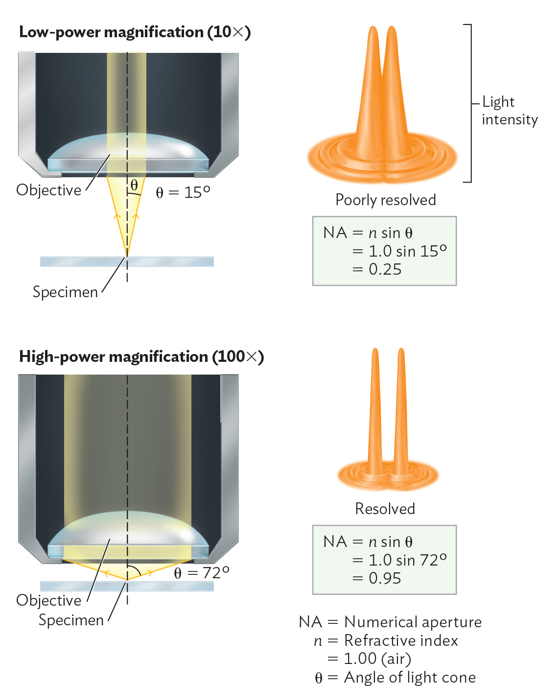
A diagram explaining resolution and numerical aperture. Two microscope objective lenses are shown. One is at low power magnification, 10 X, and the other is at high power magnification, 100 X. There is a glass slide containing a specimen some distance beneath the objective lens. At low power magnification, there is a larger distance between the specimen and the objective lens of the microscope. As a result the angle of the refracted rays entering the lens is 15 degrees. A diagram to the right shows that this results in a poorly resolved image. Two cone shaped structures are next to each other but overlap. An equation beneath reads, N A equals n sin theta equals 1 sin 15 degrees equals 0.25. At high power magnification there is a small distance between the specimen and the objective lens of the microscope. As a result the angle of the refracted rays entering the lens is 72 degrees. A diagram to the right shows that this results in a resolved image. Two cone shaped structures are next to each other and do not overlap. An equation beneath reads, N A equals n sin theta equals 1 sin 72 degrees equals 0.95. In the equations N A is the numerical aperture, n is the refractive index of air, and theta is the angle of the light cone.
To increase resolution, we must consider these factors:
Achieving the highest magnification requires a lens of high curvature and high refractive index. Figure 3.13 shows an objective lens, a lens situated directly above an object or specimen that we wish to observe at high resolution. An object at the focal point of the objective lens sits at the tip of an inverted light cone formed by rays of light through the lens converging at the object. The angle of the light cone is determined by the curvature and refractive index of the lens. The lens fills an aperture, a hole for the passage of light; for a given lens, the light cone is defined by an angle projecting from the midline of the lens. As the light cone angle increases, the horizontal width of the light cone increases, and a wider cone of light passes through the specimen. As the width of the light cone increases, the resolution improves. Therefore, the greater the angle of the light cone from a given lens, the better the resolution.
Resolution also depends on the refractive index of the medium containing the light cone, which is usually air. The refractive index (n) is the ratio of the speed of light in a vacuum to its speed in a refractive medium. For air, the refractive index is approximately 1, whereas lens material has a refractive index greater than 1. The lens bends the light, spreading it at an angle (θ, the Greek letter theta). The product of the refractive index of the medium (n) and the sine of that angle (sin θ) is the numerical aperture (NA):
NA = n sin θ
In Figure 3.13, we see the calculation of NA for objective lens magnifications of 10× and 100×. As NA increases, the magnification power of the lens increases.
As the lens power increases, the light cone widens, and the lens must come closer to the object. Defects in lens curvature become more of a problem, and focusing becomes more challenging. As the angle θ becomes very wide, too much of the light from the object is lost due to refraction at the glass-to-air interface. The highest-power objective lens, generally 100×, poses a problem in that the interface between lens and air would refract at such a wide angle that too much light would be lost (Figure 3.14). To minimize loss of light, we maintain a zone of uniform refractive index by inserting immersion oil between the lens and the slide. Immersion oil has a refractive index comparable to that of glass (n = 1.5). Using immersion oil minimizes loss of light rays at the widest angles and makes it possible to reach 100× magnification.
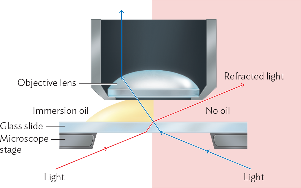
A diagram explaining the function of immersion oil in microscopy. A glass slide is sitting on top of a microscope stage. Above the slide is the objective lens. On the left side of the diagram there is immersion oil between the objective lens and the slide. On the right side there is no oil. Light is coming up from below the stage and passing through the slide. The light refracts and changes direction when it enters the glass slide. On the side with oil, the oil prevents refraction from occurring when the light exits the glass. As a result, the light rays enter the objective lens. On the side without oil, the light refracts and changes direction again when it leaves the glass slide. As a result, the light does not enter the objective lens.
The manufacture of higher-power lenses is difficult because of increased aberration (shape defects that undermine perfect parabolic curvature). For this reason, we rarely observe through a single lens. Instead we use a compound microscope, a system of multiple lenses designed to correct or compensate for aberration. A typical arrangement of a compound microscope is shown in Figure 3.15. In this arrangement, the light source is placed at the bottom, shining upward through a series of lenses, including the condenser, objective, and ocular lenses.
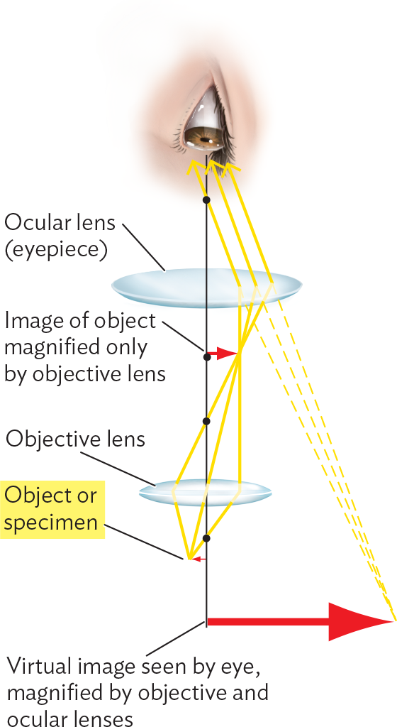
A diagram of the light path through a compound microscope. Light rays pass through the object or specimen up into the objective lens. Some distance after the objective lens, the light rays converge at a focal point. At this focal point the image of the object is magnified only by the objective lens. The light rays then separate and continue upwards to pass through these ocular lens or eyepiece. This lens refracts the light rays such that they are now all headed in the same direction. The light rays enter a human eye. Dashed lines that start at the light rays entering the eye, lead downward and converge at a point. This point is to further down and to the right of the actual specimen. This point is the virtual image seen by the eye and magnified by the objective and ocular lenses.
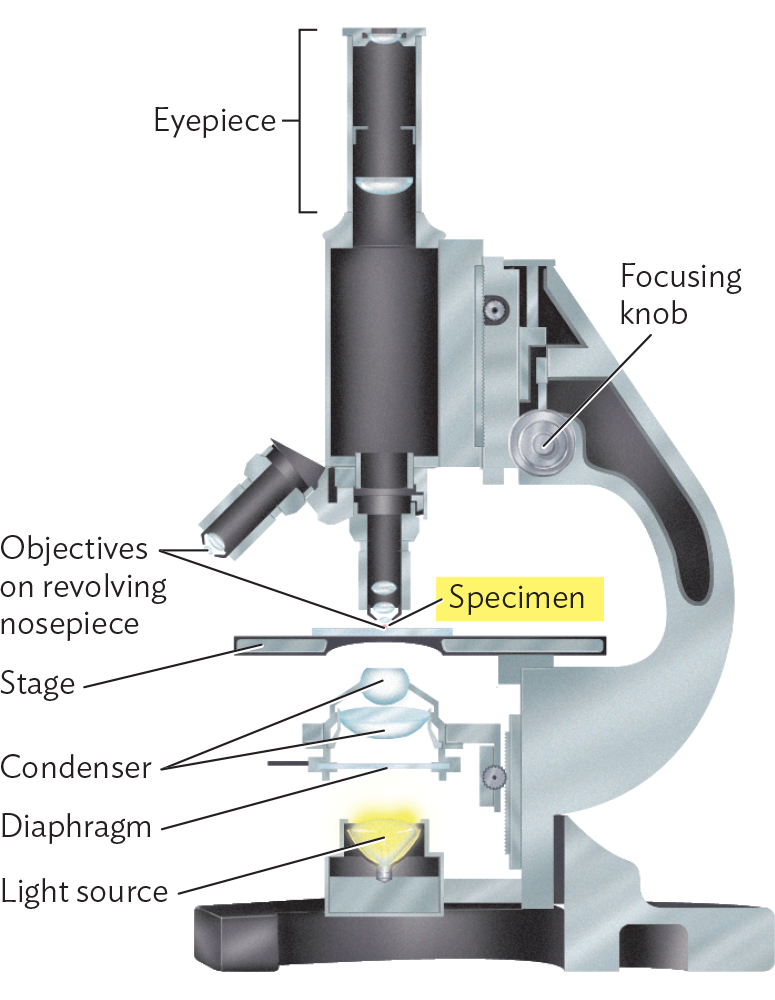
A diagram of the structure of a compound microscope. The basic structure consists of a base containing the light source connected to a curved arm that connects to the stage and to the eyepiece at the top. The eyepiece is a long cylinder that is attached to the body of the microscope. Below the body of the microscope and in line with the eyepiece are two smaller cylinders which are the objectives that are on a revolving nosepiece. Beneath the objectives is the stage, which is a horizontal plate on which a glass slide can be securely positioned. The specimen is on the glass slide. Below the stage are the condenser diaphragm and light source. A focusing knob is located at the body of the microscope where it connects to the arm.
The condenser lens focuses light rays from the light source onto a small area of the slide. Between the light source and the condenser sits a diaphragm, a device to vary the diameter of the light column. Lower-power lenses require operation at lower light levels because the excess light makes it impossible to observe the darkening effect of absorbance by the specimen (contrast). Higher-power lenses require more light and, accordingly, an open diaphragm.
The nosepiece of a compound microscope typically holds three or four objective lenses of different magnifying power, such as 4×, 10×, 40×, and 100× (requiring immersion oil). These lenses are arranged to be able to rotate in turn into the optical column. A high-quality instrument will have the lenses set at different heights from the slide so as to be parfocal. In a parfocal system, when an object is focused using one lens, it remains in focus, or nearly so, when another lens is rotated to replace the first.
The image from the objective lens is amplified by a secondary focusing step through the ocular lens. The ocular lens sits directly beneath the observer’s eye. In magnification, each light ray traces a path toward a position opposite its point of origin, thus creating an inverted image (rotated 180 degrees). We need to keep this inversion in mind when exploring a field of cells.
The magnification factor of the ocular lens is multiplied by the magnification factor of the objective lens to generate the total magnification (power). For example, a 10× ocular times a 100× objective generates 1,000× total magnification.
Observing a specimen under a compound microscope requires several steps:
An object appears in focus (that is, is situated within the focal plane of the lens) when its edge appears sharp and distinct from the background. The shape of the dark object is defined by the points of light surrounding its edge. The partial resolution of these points of light generates extra rings of light surrounding an object whose dimensions are close to the resolution limit (Figure 3.16).
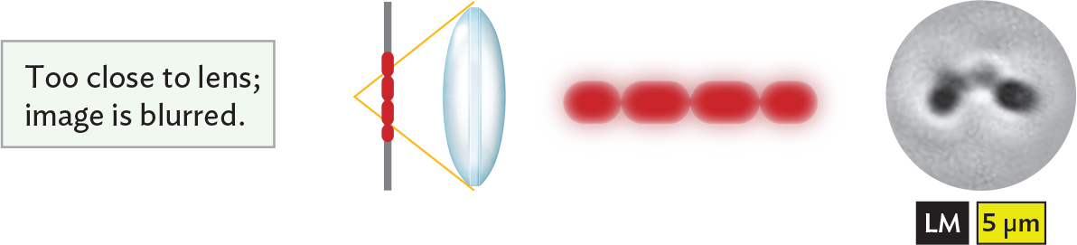
An illustration showing that an image is blurred when the object is too close to the lens. There is a vertical slide positioned parallel to a glass biconvex lens. The specimen, a chain of red cells, is centered on the slide. Light rays passing through the lens converge at a focal point behind the specimen. The specimen is too close to the lens, and as a result, the image is blurred. The chain of cells can be seen, but it has a low quality of detail so it is difficult to distinguish individual cells in the chain and their shapes.

An illustration showing that an image is sharp when the object lies within the focal plane of the lens. There is a vertical slide positioned parallel to a glass biconvex lens. The specimen, a chain of red cells, is centered on the slide. Light rays passing through the specimen and lens converge at the specimen. The specimen is in focus, so as a result, the image appears sharp. A chain of ovoid cells is seen with enough detail that the individual cells of the chain can be distinctly identified. The edges of the chain are sharp and stand out from the background.
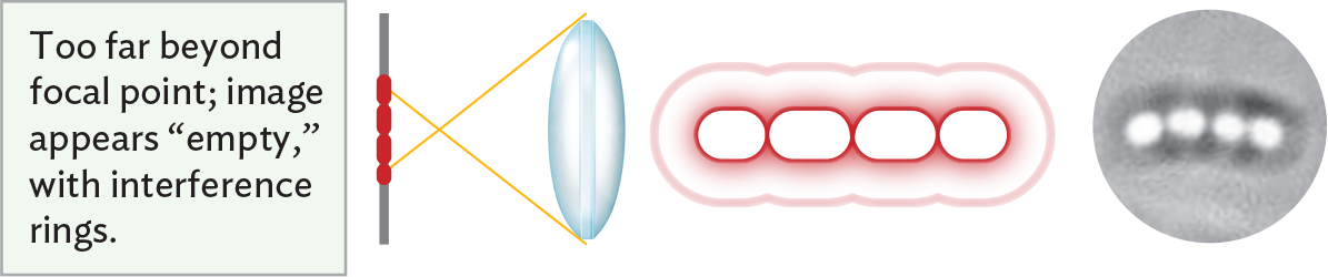
An illustration showing that an image appears empty when an object is too far beyond the focal point of the lens. There is a vertical slide positioned parallel to a glass biconvex lens. The specimen, a chain of red cells, is centered on the slide. Light rays passing through the specimen and the lens converge at a focal point between the specimen and lens. The specimen is too far beyond the focal point, so as a result, the image appears empty with interference rings. There is a chain of ovoid cells with clear white centers and dark, fuzzy borders. A thinner ring extends beyond the outer borders of the cells to surround the chain. Though the individual cells can be roughly identified, their true sizes and shapes are distorted by the focal effect.
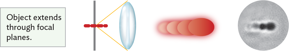
An illustration showing multiple image effects when an object extends through focal planes. There is a vertical slide positioned parallel to a glass biconvex lens. The specimen, a chain of red cells, is centered on the slide at an angle perpendicular to the slide and lens. Light rays passing through the specimen and lens converge at a focal point on the specimen. Because the object, or specimen, extends through focal planes, a variety of focal effects are seen. A series of cells, which may or may not be in a chain appear to be stacked on each other, partially overlapping. Some of the cells are blurry, others are well defined, and one appears to have a hollow center.
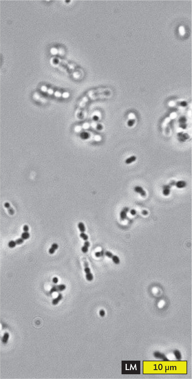
A light micrograph of a wet mount of Oenococcus oeni. There are multiple chains of spherical cells across the field of view. Chains are about 8 micrometers in length and each individual cell has a diameter of about 2 micrometers. The quality of detail varies significantly across the slide. Some of the chains are in focus, with the cells appearing dark and well defined. Other chains are not in focus, appearing blurry or having cells which appear to have hollow centers. A few chains show a mixture of these effects throughout the chain.
Figure 3.16 presents microscopic images of Oenococcus oeni, a species of bacteria that ferment grapes during winemaking. The bacteria are observed in a wet mount, a drop of water on a slide with a coverslip. The advantage of the wet mount is that the organism is viewed in as natural a state as possible, without artifacts resulting from chemical treatment. The disadvantage is that most living cells are transparent and therefore show little contrast with the external medium.
As bacterial cells drift in and out of the focal plane, their appearance changes through optical effects. When the bacteria move out of the focal plane too close to the lens, resolution declines and the image blurs (Figure 3.16A). When the bacteria move within the focal plane, the image appears sharp, with a bright line along the edge of the cells. Each chain of cells shows well-focused portions along with hazier portions that are too close to the lens (Figure 3.16B). When the cells move too far past the focal plane, the shape may appear bright or “hollow” (Figure 3.16C). In fact, the bacteria are not hollow at all; only the magnified image has changed.
At highest magnification, the focal plane is so narrow that only part of each chain of bacteria can be seen in focus. As a result, different parts of the cells appear out of focus (either too near or too far from the lens; Figure 3.16D). When the end of a rod or chain points toward the observer, it appears round and dark. Light travels through the length of the cell before reaching the observer, so the cell absorbs more light and appears darker.
SECTION SUMMARY
— The wavelength of light, which limits resolution to about 0.2 µm.
— The magnifying power of a lens, which depends on its numerical aperture (n sin θ).
— The position of the focal plane, which is the location where the specimen is “in focus” (that is, where the sharpest image is obtained).
Thought Question 3.2 In theory, which angle of the light cone would produce the highest resolution? What practical problem would you have in designing a lens to generate this light cone?
In theory, an angle of 90° for the light cone would produce the highest resolution. However, a 90° angle generates a cone of 180°—that is, a cone collapsed flat. Such a “cone” would require the object to sit in the same position as the objective lens—in other words, to have a focal distance of zero. In practice, the cone of light needs to be somewhat less than 180° to allow room for the object and to avoid substantial aberrations (light-distorting properties) in the lens material.
Thought Question 3.3 Under starvation conditions, bacteria such as Bacillus thuringiensis, the biological insecticide, repackage their cytoplasm into endospores, leaving behind an empty cell wall. Suppose, under a microscope, you observe what appears to be a hollow cell. How can you tell whether the cell is indeed hollow or whether it is simply out of focus?
You can tell whether the cell is out of focus or actually hollow by rotating the fine-focus knob to move the objective up and down while observing the specimen carefully. If the hollow shape appears to be the sharpest image possible, it is probably a hollow cell. If the hollow shape turns momentarily into a sharp, dark cell, it was probably a full cell out of focus before.