Microscopy: Optics and Properties of Light
2.2 Optics and Properties of Light
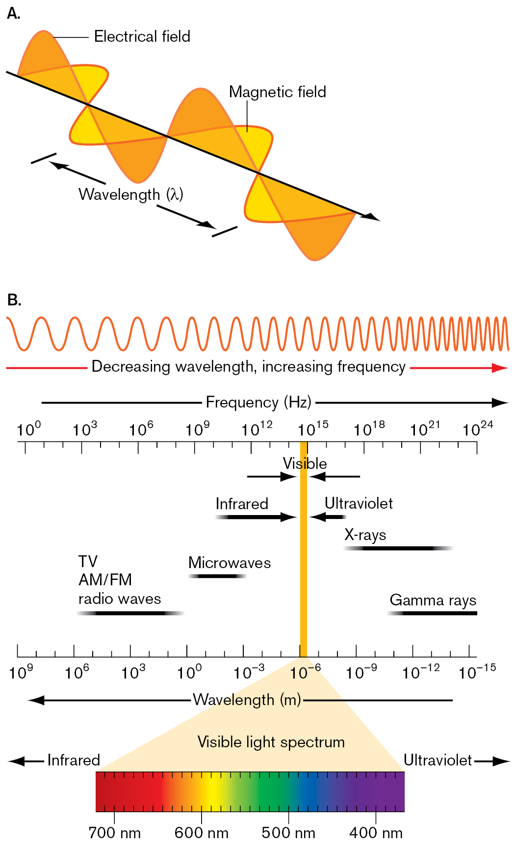
How do light rays magnify an image? Light microscopy directly extends the lens system of our own eyes. Light is part of the spectrum of electromagnetic radiation (Fig. 2.8), a form of energy propagated as waves that are associated with electrical and magnetic fields. Regions of the electromagnetic spectrum are defined by wavelength, which for visible light is about 400–750 nm. Radiation of longer wavelengths includes infrared and radio waves, whereas shorter wavelengths include ultraviolet rays and X-rays.
More information
Two illustrations describe electromagnetic radiation and the electromagnetic spectrum.
An illustration shows the wavelengths of electrical and magnetic fields. Electrical field waves and magnetic field waves both progress along a line with synchronized peaks and troughs. However the waves are perpendicular to each other. The distance between peaks of the magnetic field is labeled as wavelength in lambda.
An illustration shows the electromagnetic spectrum. It consists of a frequency wave representing Decreasing wavelength, increasing frequency. A scale below represents frequency in hertz ranges from 10 superscript 0 to 10 superscript 24 in increments of 10 superscript 3. Another scale at the bottom represents wavelength in meters ranging from 10 superscript 9 to 10 superscript negative 15 in decrements of superscript 3. A vertical bar is drawn between the two scales at 10 superscript minus 6 meters to 10 superscript 15 Hertz. The vertical bar represents the visual spectrum. A colored scale at the bottom shows a visible light spectrum ranges from 700 nanometers to 400 nanometers in decrements of 100 nanometers. It is indicated that to infrared waves extend beyond 700 nanometers and ultraviolet waves extend below 400 nanometers. Microwaves fall between 10 superscript 0 to 10 superscript negative 3 meters in wavelength, and between 10 superscript 9 to 10 superscript 12 Hertz in frequency. TV AM or FM radio waves fall between 10 superscript 6 to superscript 0 meters in wavelength, and between 10 superscript 3 to 10 superscript 9 Hertz in frequency. X rays fall between 10 superscript negative 9 to 10 superscript negative 14 meters in wavelength, and between 10 superscript 18 to 10 superscript 23 Hertz in frequency. Gamma rays fall between 10 superscript negative 11 to 10 superscript 10 negative 15 meters in wavelength, and between 10 superscript 20 to 10 superscript 24 Hertz in frequency.
Light Carries Information
All forms of electromagnetic radiation carry information from the objects they interact with. The information carried by radiation can be used to detect objects; for example, radar (using radio waves) detects a speeding car. All electromagnetic radiation travels through a vacuum at the same speed: about 3 × 10⁸ meters per second (m/s), the speed of light. The speed of light (c) is equal to the wavelength (λ) of the radiation multiplied by its frequency (ν), the number of wave cycles per unit time:
c = λν
Because c is constant, the longer the wavelength λ is, the lower the frequency ν is. Frequency is usually measured in hertz (Hz), reciprocal seconds (1/s).
The wavelength λ limits the size of objects that can be resolved as separate from neighboring objects. Resolution requires:
- Contrast between the object and its surroundings. Contrast is the difference in light and dark. If an object and its surroundings absorb or reflect radiation equally, then the object will be undetectable. It is hard to observe a cell of transparent cytoplasm floating in water, because the aqueous cytoplasm and the extracellular water tend to transmit light similarly, producing little contrast.
- Wavelength smaller than the object. For an object to be resolved, the wavelength of the radiation must be equal to or smaller than the size of the object. If the wavelength of the radiation is larger than the object, then most of the wave’s energy will simply pass through the object, like an ocean wave passing around a dock post. Thus, radar, with a wavelength of 1–100 centimeters (cm), cannot resolve microbes, though it easily resolves cars and people.
- Magnification. The human retina absorbs radiation within a range of wavelengths, 400–750 nm (0.40–0.75 µm), which we define as visible light. But the smallest distance our retina can resolve is 150 µm, about 300 times the wavelength of light. Thus, we are unable to access all of the information contained in the light that enters our eyes. To use more of the information carried within the light, we must spread the light rays apart far enough for our retina to perceive the resolved image.
Light Interacts with an Object
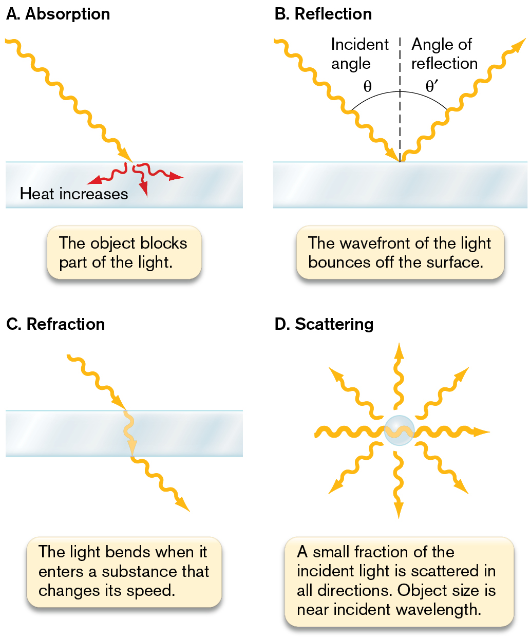
The physical behavior of light resembles in some ways a beam of particles and in other ways a waveform. The particles of light are called photons. Each photon has an associated wavelength that determines how the photon will interact with a given object. The combined properties of particle and wave enable light to interact with an object in several different ways (Fig. 2.9  ).
).
More information
Four illustrations of different light with matter interactions. The first illustration demonstrates absorption. The second illustration demonstrates reflection. The third illustration demonstrates refraction. The fourth illustration demonstrates scattering.
An illustration labeled A shows absorption. It consists of a horizontal bar, in which a wave-shaped arrow from the top left falls on the bar and produces three different arrows within the bar labeled heat increases. The wave shaped bar represents light and the horizontal bar represents matter. The corresponding text reads the object blocks part of life.
An illustration labeled B shows reflection. It consists of a horizontal bar, in which a vertical dashed line is drawn on the midpoint of the bar. A wave-shaped arrow from the top left reaches the bar at the midpoint at an angle of incident angle theta. Another arrow from the right side of the midpoint extends upward at the same angle and exits at the top right. The angle between the dashed line and the second arrow is the angle of reflection theta prime. The horizontal bar represents matter and the wave-shaped arrow represents light. The text reads the wavefront of the light bounces off the surface.
An illustration labeled C shows refraction. It consists of a horizontal bar, in which the arrow representing light enters from the top left at an angle, travels vertically through the bar, and exits the other side of the bar at an angle. The horizontal bar represents matter. The corresponding text reads the light bends when it enters a substance that changes its speed.
An illustration labeled D shows scattering. It consists of a sphere in which the light from the left passes into the sphere and exits the right. Three arrows exit the top of the sphere, and three other arrows exit the bottom of the sphere. The corresponding text reads a small fraction of the incident light is scattered in all directions. Object size is near incident wavelength.
- Absorption means that the absorbing object gains the photon’s energy (Fig. 2.9A). The energy is converted to a different form, usually heat. (That is why a live specimen eventually “cooks” on the slide if observed for too long.) When a microbial specimen absorbs light, it can be observed as a dark spot against a bright field, as in bright-field microscopy. Some molecules that absorb light of a specific wavelength reemit energy as light with a longer wavelength; this is called fluorescence. Fluorescence microscopy is discussed in Section 2.5.
- Reflection means that the wavefront redirects from the surface of an object at an angle equal to its incident angle (Fig. 2.9B). The reflection of light waves is analogous to the reflection of water waves. Reflection from a silvered mirror or a glass surface is used in the optics of microscopy.
- Refraction means that light bends as it enters a substance that slows its speed (Fig. 2.9C). Such a substance is said to be refractive and, by definition, has a higher refractive index than air has. Refraction is the key property that enables a lens to magnify an image.
- Scattering means that a portion of the wavefront is converted to a spherical wave originating from the object (Fig. 2.9D). If a large number of particles simultaneously scatter light, we see a haze; for example, the haze of bacteria suspended in a culture tube. Special optical arrangements can use scattered light to detect (but not resolve) microbial shapes smaller than the wavelength of light.
Magnification by a Lens
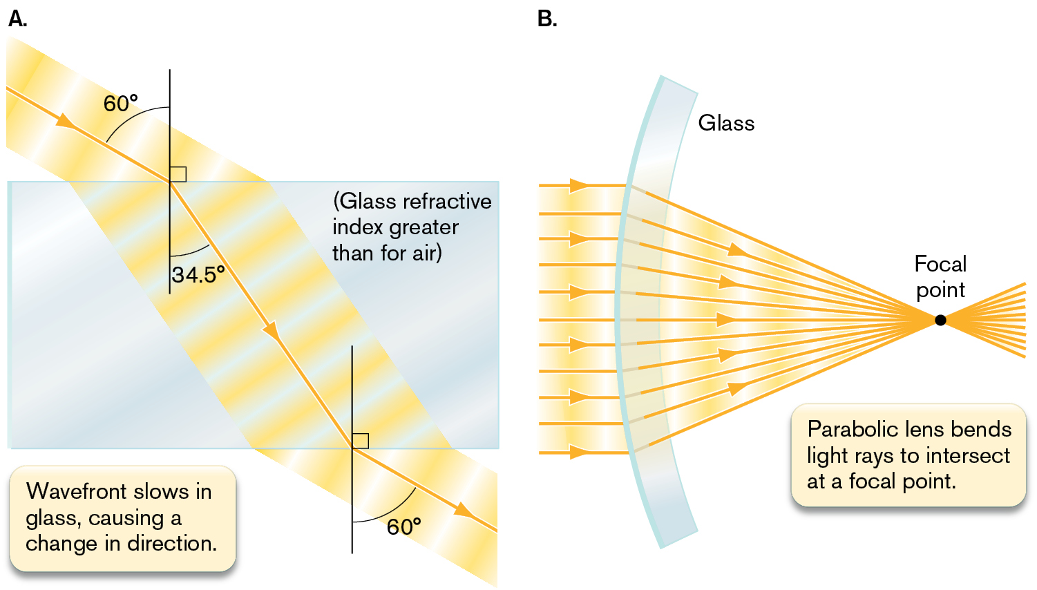
Magnification requires the bending of light rays, as in refraction. As a wavefront of light enters a refractive material, such as glass, the region of the wave that first reaches the material is slowed, while the rest of the wave continues at its original speed until it also passes into the refractive material (Fig. 2.10A ). As the entire wavefront passes through the refractive material, its path continues, bent at an angle from its original direction.
Thought Question
2.3 Explain what happens to the refracted light wave as it emerges from a piece of glass of even thickness. How do its new speed and direction compare with its original (incident) speed and direction?
 ANSWER
 ANSWER
The part of the wavefront that emerges first travels faster than the portion still in the glass, causing the wavefront to bend toward the surface of the glass. Ultimately, the wave travels in the same direction and with the same speed as it did before entering the glass. The path of the emerging light ray is parallel to the path of the light ray entering the glass and is shifted over by an amount dependent on the thickness of the glass. This refraction will alter the path of the beam of light and decrease the amount of light reaching the lens of the microscope. Immersion oil has the same refractive index as glass and will limit the amount of light lost in this way.
How does refraction accomplish magnification? Refraction magnifies an image when light passes through a refractive material shaped so as to spread its rays. One shape that spreads light rays is a parabolic curve. When light rays enter a lens of refractive material with a parabolic surface (Fig. 2.10B), parallel rays each bend at an angle such that all of the rays meet at a certain point, called the focal point. From the focal point behind the lens, the light rays continue, spreading out with an expanding wavefront. This expansion magnifies the image carried by the wave. The distance from the lens to the focal point (called the focal distance) is determined by the degree of curvature of the lens and by the refractive index of its material.
More information
Two illustrations show the refraction of light waves.
An illustration shows light rays entering glass at an angle of 60 degrees. The corresponding text reads glass refractive index is greater than that of air, and the wavefront slows in glass, causing a change in direction. The light ray in the illustration shifts to an an angle of 34.5 degrees as it passes through the glass. It exits from the bottom of the glass at an angle of 60 degrees.
An illustration shows light as it travels through a glass parabolic lens. Several parallel light rays enter into the concave glass from the left and exit on the right at different angles such that they intersect at a single point toward the right labeled as a focal point. The corresponding text reads the parabolic lens bends light rays to intersect at a focal point.
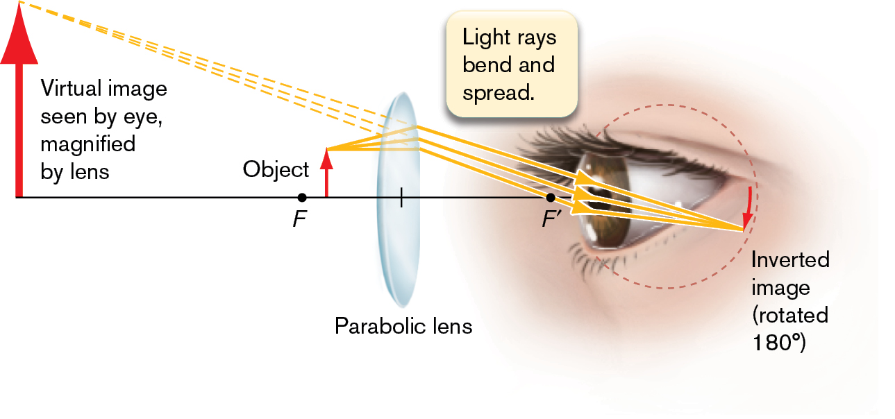
In Figure 2.11 , the object under observation is placed near the focal point (F) in front of a lens. The light rays trace a path opposite to that of Figure 2.10B. The rays expanding from point F are bent by the lens into a nearly parallel path entering the eye. The eye perceives the expanded light rays as a virtual image; that is, an image that appears to represent a much larger object farther away. The expansion of light rays, or magnification, increases the distances between points of the image. The details of the magnified image become larger than the spacing of photoreceptor units in the retina. Thus our eye can perceive details that the unaided eye cannot see.
More information
An illustration shows the magnification of an image through a lens. A horizontal line is shown. A dot at the center of the line is labeled as F, and another dot on the right side of the line is labeled as F prime. To the right of the F an upward arrow appears, labeled as an object, and to the right of the object, a parabolic lens is shown. Another upward arrow is placed at the left end of the line, and the corresponding text reads a Virtual image seen by eye, magnified by lens. An image of a human eye appears at the right end of the line to view the object and is labeled as an inverted image, rotated 180 degrees. Three dashed lines from the object arrow fall on the lens, and the inverted image is seen through the eye. A note reads light rays bend and spread.
Resolution of Detail
What limits the effect of magnification? The spreading of light rays does not in itself increase resolution. For example, an image composed of dots does not gain detail when enlarged on a photocopier, nor does an image composed of pixels gain detail when enlarged on a computer screen. In these cases, magnification fails to show details because the individual details of the image expand in proportion to the expansion of the overall image. Magnification without increasing detail is called empty magnification.
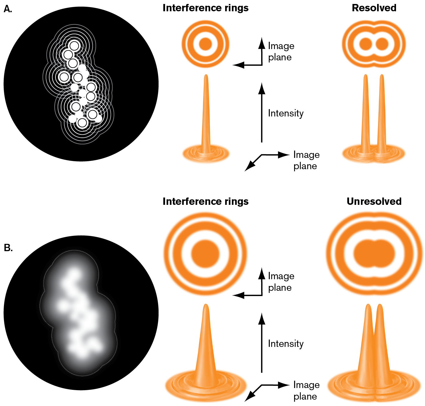
The resolution of detail in microscopy is limited by the wave nature of light. In theory, a perfect lens that focuses all of the light from an object should form a perfect image as its rays converge through the focal point. But light rays actually form wavefronts of infinite extent. Because the width of the lens is finite, only part of the wavefront enters, causing interference. The converging edges of the wave interfere with each other to form alternating regions of light and dark (Fig. 2.12 ). Thus, a point source of light (such as a point of detail in a specimen) forms an image of a bright central peak surrounded by interference rings of light and dark. Even a well-focused bright object appears as a bright disk surrounded by faint rings.
Suppose an object consists of a collection of point sources of light. Each point source generates a central peak of intensity. The width of this central peak will define the resolution, or separation distance, between any two points of the object (Fig. 2.12). This resolution determines the degree of detail that can be observed. In practice, any object, such as a stained microbe against a bright field, can be considered a large collection of points of light that act as partly resolved peaks of intensity.
More information
Two illustrations explain interference rings that are resolved versus unresolved.
An illustration depicts narrow interference rings with peaks that are well resolved. It consists of the focal points of light waves that exist in a dark circle. The focal points are represented as lighter dots with distinct ripples. To the right shows the interference rings and resolved rings. The interference rings consist of concentric circles and a bidirectional arrow reads image plane. An image of a narrow peak consists of an upward arrow labeled as intensity, and the bidirectional arrow is labeled as an image plane. In resolved, there are two distinct points that have overlapping concentric rings when viewed in the image plane. When viewed from the side, two distinct narrow peaks are visible.
An illustration depicts wide interference rings with peaks that are unresolved. A large circle with a white shaded region in the center. To the right shows two columns labeled interference rings and unresolved. In the interference ring, a large concentric circle is in the image plane. Below, a wider peak consists of an upward arrow labeled as intensity and a bidirectional arrow labeled as the image plane is at the bottom. In the unresolved example, two circles in the middle overlap and can not be differentiated. Below, two peaks overlap at their bases even though their top points are distinct.
What factors limit resolution of an image? The wavelength of light limits the sharpness of the peak intensity of a point of detail. The finite width of the wavefront captured by the lens leads to interference and widens the peak intensity. Thus, bright-field light microscopy resolves only details that are greater than half the wavelength of light, about 200 nm (0.2 µm). Nevertheless, in advanced optical methods such as fluorescence microscopy (see Section 2.5), computation can extract positional detail from light rays. Such methods, called super-resolution imaging, enable us to track cellular molecules at a precision of 20–40 nm (discussed in Section 2.5).
To Summarize
- Electromagnetic radiation interacts with an object and acquires information we can use to detect the object. Contrast between object and background makes it possible to detect the object and resolve its component parts.
- The wavelength of the radiation must be equal to or smaller than the size of the object for a microscope to resolve the object’s shape.
- Absorption means that the energy from light (or other electromagnetic radiation) is acquired by the object. Reflection means that the wavefront bounces off the surface of a particle at an angle equal to its incident angle. Scattering means that a wavefront interacts with an object of smaller dimension than the wavelength. Light scattering enables the detection of objects whose detail cannot be resolved.
- Refraction is the bending of light as it enters a substance that slows its speed. Refraction through a curved lens magnifies an image, enlarging its details beyond the spacing between our eye’s photoreceptors.
- Interference between wavefronts converts a point source of light to a peak of intensity surrounded by rings. The width of the peak limits the resolution of details of an image.
Glossary
- electromagnetic radiation
- Energy radiating in the form of alternating electrical and magnetic waves, quantized in photons.
- contrast
- Differential absorption or reflection of electromagnetic radiation between an object and a background that allows the object to be distinguished from the background.
- absorption
- In optics, the capacity of a material to absorb light.
- fluorescence
- Also called epifluorescence. The emission of light from a molecule that absorbed light of a shorter, higher-energy wavelength.
- reflection
- The deflecting of an incident light ray by an object, at an angle equal to the incident angle.
- refraction
- The bending and slowing of light as it passes through a substance.
- refractive index
- The degree to which a substance causes the refraction of light; a ratio of the speed of light in a vacuum to its speed in another medium.
- scattering
- Interaction of light with an object that results in propagation of spherical light waves at relatively low intensity.
- lens
- An object composed of transparent, refractive material that bends light rays to converge at a focal point (or to diverge from an imaginary point). For electron microscopy, a series of magnets arranged as a magnetic lens bends electron beams to converge or diverge.
- focal point
- The position at which light rays that pass through a lens intersect.
- empty magnification
- Magnification without an increase in resolution.
- interference
- The interaction of two wavefronts. Interference can be additive (amplitudes in phase, constructive) or subtractive (amplitudes out of phase, destructive).
- super-resolution imaging
- Techniques of microscopy that pinpoint the location of an object with a precision greater than the resolution of ordinary optical or fluorescence microscopy.