We have introduced the major structures that cells need to contain and organize their contents, maintain their DNA, and synthesize new parts. Besides these fundamental structures, different species have evolved specialized devices adapted to diverse metabolic strategies and environments. And microscopy continually reveals new microbial structures whose functions remain a mystery (Special Topic 3).
Thylakoids, Carboxysomes, and Storage Granules
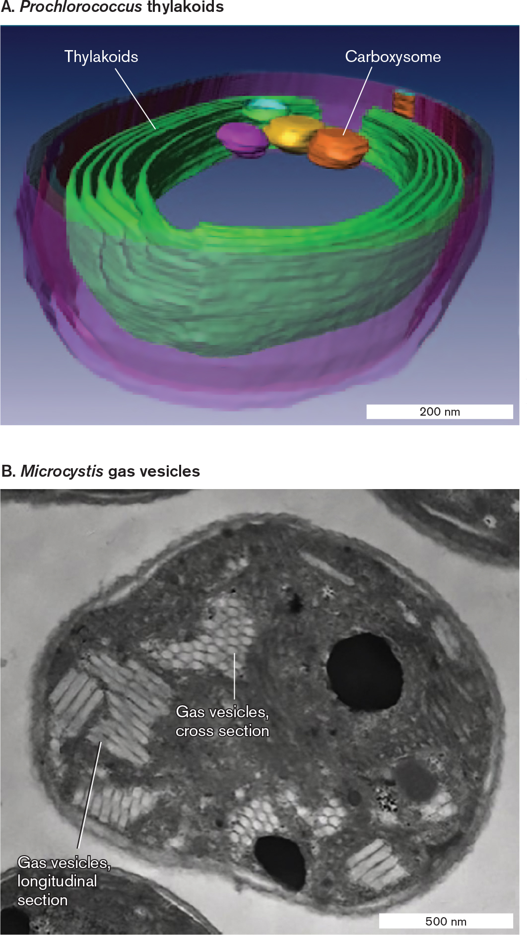
Cyanobacteria are phototrophs that produce food and oxygen for marine and freshwater ecosystems; their diversity is explored in Section 18.2. In the water, cyanobacteria must absorb sufficient amounts of light to drive photosynthesis (see Section 14.6). To maximize the collecting area of their photosynthetic membranes, cyanobacteria have evolved specialized systems of extensively folded intracellular membrane called thylakoids (Fig. 3.36A). Thylakoids consist of layers of folded sheets (lamellae) or tubes of membranes packed with chlorophylls and electron carriers. Cyanobacteria containing thylakoids structurally resemble eukaryotic chloroplasts, which evolved from a common ancestor of modern cyanobacteria.
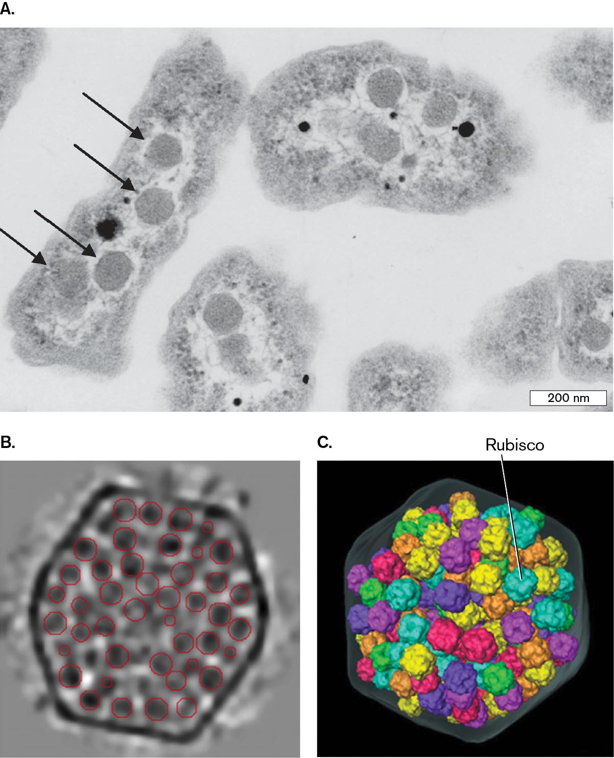
The thylakoids conduct only the “light reactions” of photon absorption and energy storage. The energy obtained is rapidly spent to fix carbon dioxide—a process that occurs within carboxysomes (Fig. 3.36A; see also Fig. 15.7). Carboxysomes are polyhedral, protein-covered bodies packed with the enzyme Rubisco for CO2 fixation (see Section 15.2).
How do phototrophs keep themselves at the top of the water column? Some bacteria and archaea form gas vesicles to increase buoyancy and keep the cell afloat. Figure 3.36B shows a cross section of Microcystis, a cyanobacterium that forms toxic algal blooms in lakes polluted by agricultural runoff. Microcystis shows typical gas vesicles, which are hollow protein structures that collect gases. The gases are hydrogen or carbon dioxide produced by the cell’s metabolism. Each vesicle consists of a tube of protein with two conical ends. The tubes pack in hexagonal arrays.
More information
A model and a micrograph identify organelles in two species of phototrophic bacteria.
A model generated from cryo-electron microscopy of thylakoids in Prochloroccus. The bacterium is a coccus shape of about 400 nanometers in diameter. The outer membrane is visible. Interior to the outer membrane are thin membrane layers identified as thylakoids. Carboxysomes are also identified in a cluster at one end of the cell. The carboxysomes are irregularly shaped spherical structures.
A transmission electron micrograph of gas vesicles inside Microcystis. The bacterium is a round shape of about 1000 nanometers in diameter. Lighter sections of the bacteria are identified as gas vesicles. Gas vesicle cross sections appear as irregular shapes with patterned surfaces. Gas vesicle longitudinal sections appear as irregular shapes with evenly spaced horizontal lines across the surfaces.
FIGURE 3.36 ■Organelles of phototrophs.A. The marine phototroph Prochlorococcus contains photosynthetic double membranes called thylakoids. Carboxysomes are polyhedral, protein-covered bodies packed with the Rubisco enzyme for CO2 fixation (cryo-EM). B.Microcystis gas vesicles (protein) in hexagonal arrays. Gas vesicles provide buoyancy, enabling the phototroph to remain at the surface of the water, exposed to light (TEM). Source: Part A from Clare Ting. 2007. J. Bacteriol.189:4485.C. S. TING ET AL. 2007. J BACTERIOL.189:4485–4493ALYSSA MLOUKA ET AL. 2004. J. BACTERIOL.186:2355
When light is scarce, cyanobacteria may digest their thylakoids for energy and as a source of nitrogen. Alternatively, the cell may digest energy-rich materials from storage granules composed of glycogen or other polymers, such as polyhydroxybutyrate (PHB) and poly-3-hydroxyalkanoate (PHA). PHB and PHA polymers are of interest as biodegradable plastics, and bacteria have been engineered to produce them industrially. Similar storage granules are also produced by nonphototrophic soil bacteria.
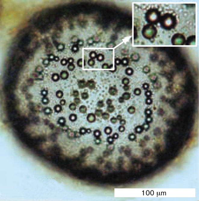
Another type of storage device is sulfur—granules of elemental sulfur produced by purple and green phototrophs through photolysis of hydrogen sulfide (H2S). Instead of disposing of the sulfur, the bacteria store it in granules, such as those of the giant sulfur-oxidizing bacterium Thiomargarita namibiensis (Fig. 3.37). Sulfur-reducing bacteria also make sulfur globules; for example, by reducing sulfate (SO42−) to sulfur. The sulfur granules may later be used as an oxidant when reduced substrates are available (see Chapter 14). And the presence of potentially toxic sulfur granules may help cells avoid predation.
More information
A micrograph of sulfur globules in the cytoplasm of Thiomargarita namibiensis. The bacterium is a coccus shape of about 200 micrometers in diameter. The outer edge of the cell is thick and dark. Within the cell are several spheres with brightly lit centers and dark perimeters. The spheres appear to be randomly scattered across the cell.
FIGURE 3.37 ■Intracellular sulfur globules. Sulfur globules dot the cytoplasm of Thiomargarita namibiensis, an anaerobic, thermophilic bacterium that gains energy by oxidizing hydrogen sulfide (H2S) to elemental sulfur (S0).
Source: Heide N. Schulz and Horst D. Schulz. 2005. Science307:416–418.
H. N. SCHULZ ET AL. 2005. SCIENCE.307:416–418
Pili and Stalks
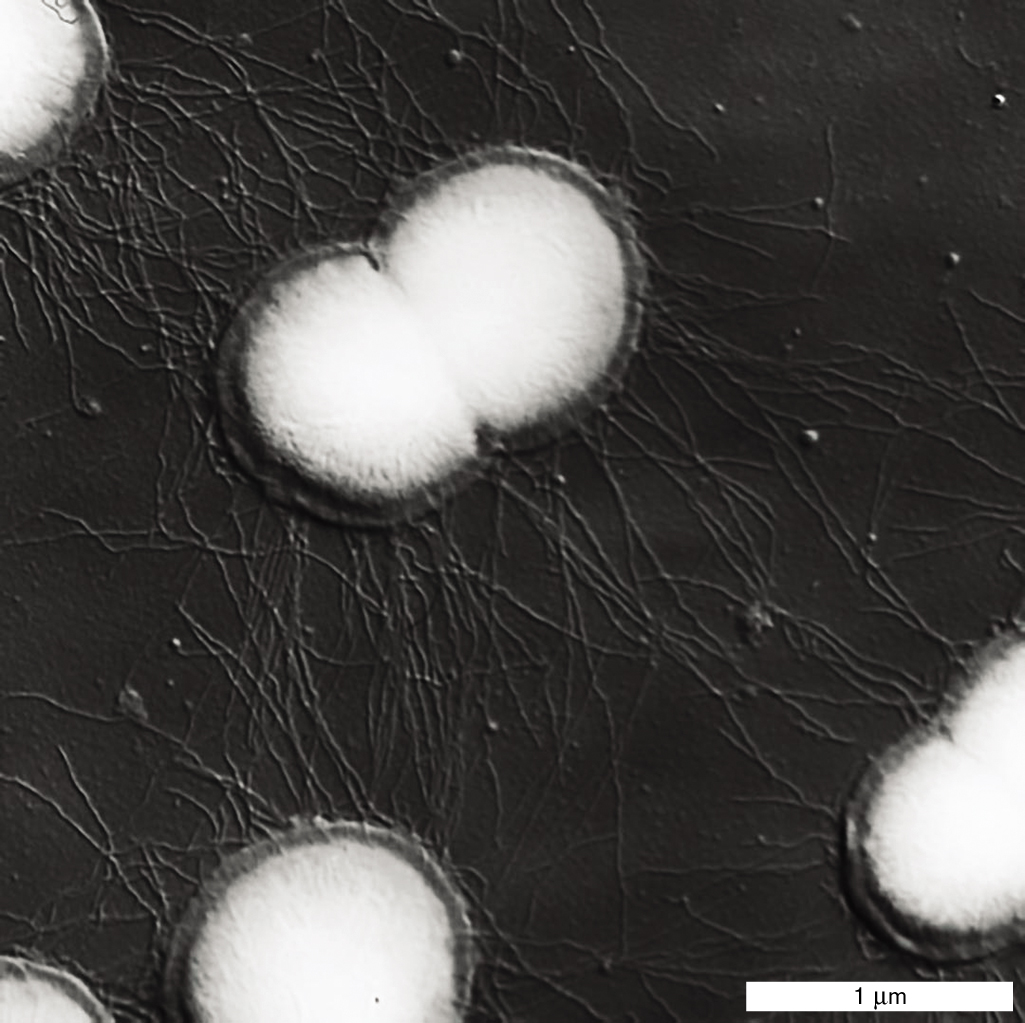
In a favorable habitat, such as a running stream full of fresh nutrients or the epithelial surface of a host, it is advantageous for a cell to adhere to a substrate. Adherence, the ability to attach to a substrate, requires specific structures. A common adherence structure is the pilus (plural, pili), which is constructed of straight filaments of protein monomers called pilin. Short attachment pili are also called fimbriae. For example, the sexually transmitted pathogen Neisseria gonorrhoeae uses pili to attach to the mucous membranes of the reproductive tract (Fig. 3.38). Pili can also provide a form of motility called “twitching,” in which the pili act as limbs to “walk” the bacterium across a substrate (presented in Chapter 4). Bacteria such as Pseudomonas aeruginosa use twitching motility to begin biofilm formation (discussed in Section 4.5).
More information
An electron micrograph shows the attachment of protein filaments. It consists of a pinched oval-shaped cell, of about 1 micrometer in length and 0.75 micrometer in width. The cell is connected to other round cells by thin, hair-like tendrils of pili. The pili are longer than 1 micrometer.
FIGURE 3.38 ■Pili are protein filaments for attachment.Neisseria gonorrhoeae, cause of the sexually transmitted infection gonorrhea, use pili to attach to the host mucous membrane (SEM). L. CRAIG ET AL. 2006. MOL. CELL23:651–662
In Gram-negative enteric bacteria, pili of a different kind, also called the sex pili, attach a donor cell to a recipient cell for transfer of DNA. This process of DNA transfer is called conjugation. The genetic consequences of conjugation are discussed in Chapter 9.
A different kind of attachment organelle is an extension of the envelope and cytoplasm called a stalk, seen earlier in the stalked cell of Caulobacter (Fig. 3.30). The tip of the stalk secretes adhesion factors that form a “holdfast,” which firmly attaches the bacterium in an environment that has proved favorable. A stalk and holdfast enable iron-oxidizing bacteria to form large biofilms in streams contaminated by iron drainage. The biofilms become coated by orange iron hydroxides, tinting the stream orange.
Rotary Flagella
What happens when the cell’s environment runs out of nutrients or becomes filled with waste? In rapidly changing environments, cell survival requires motility, the ability to move and relocate. Many bacteria and archaea can swim by means of rotary flagella (singular, flagellum). Flagellar motility benefits the cell by causing the population to disperse, decreasing competition. Motility also enables cells to swim toward a favorable habitat (by chemotaxis, discussed shortly).
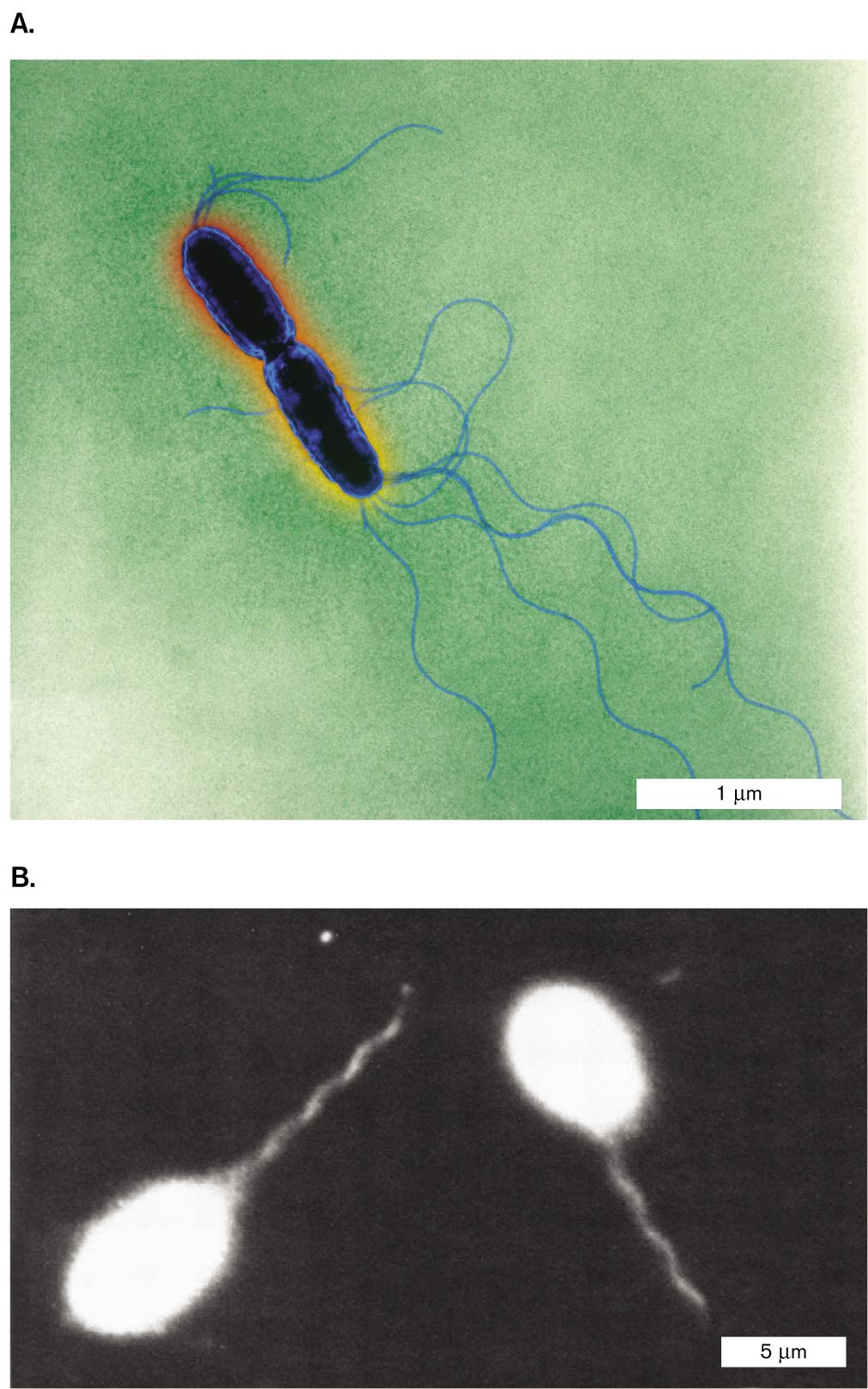
Flagellar motility. Flagella are helical propellers that drive the cell forward like the motor of a boat. Howard Berg (1934–2021) at the California Institute of Technology originally described the bacterial flagellar motor, which was the first rotary device to be discovered in a living organism. Different bacterial species have different numbers and arrangements of flagella. Peritrichous cells, such as Escherichia coli and Salmonella species, have flagella randomly distributed around the cell (Fig. 3.39A). The flagella rotate together in a bundle behind the swimming cell (Fig. 3.39B). Lophotrichous cells, such as Rhodospirillum rubrum, have flagella attached at one or both ends. In monotrichous (polar) species, such as the Caulobacter swarmer cell (see Fig. 3.30), the cell has a single flagellum at one end.
More information
Two micrographs of Flagellated Salmonella enterica.
A transmission electron micrograph of Salmonella enterica. Two rod shaped cells are connected. Each cell is about 1 micrometer long and 0.25 micrometer wide. Each cell has several thin strands of flagella extending from the unconnected end. The flagella are longer than 1 micrometer.
A dark-field micrograph of Salmonella enterica. Two rod shaped cells are visible in the micrograph. Each cell is about 5 micrometers long and 3 micrometers wide. The cells appear blurry and no internal details can be made out. Each cell has a single thin stranded flagellum attached at one end. The flagella are each longer than 5 micrometers.
FIGURE 3.39 ■Flagellated Salmonella bacteria.A.Salmonella enterica has multiple flagella (colorized TEM). B. The flagella collect in a bundle behind a swimming cell. Under dark-field microscopy, the cell body appears overexposed, about five times as large as the actual cell. KWANGSHIN KIM/SCIENCE SOURCEROBERT MACNAB. 1976.J. CLIN. MICROBIOL.4:258
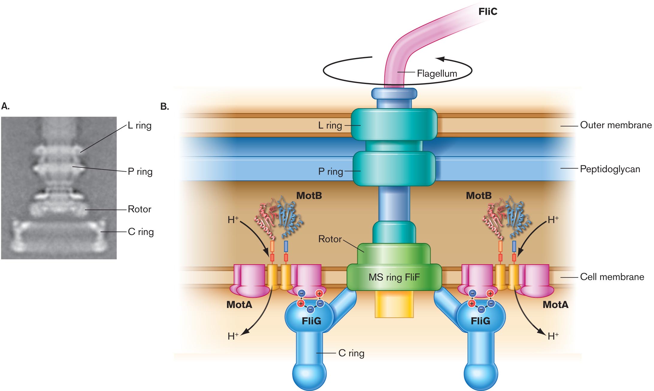
How does a rotary flagellum work? Each flagellum has a spiral filament of protein monomers called flagellin (protein FliC). The filament actually rotates by means of a motor driven by the cell’s transmembrane proton current—the same proton potential that drives the membrane-embedded ATP synthase (presented in Chapter 14). The flagellar motor is embedded in the layers of the cell envelope (Fig. 3.40). The motor possesses an axle and rotary parts, all composed of specific proteins. For example, protein MotB forms part of the ion channel whose flux of hydrogen ions powers rotation. Another protein, FliG, forms part of the device that generates torque (rotary force). Much of the motor’s structure and function was elucidated by Scottish microbiologist Robert Macnab (1940–2003) at Yale University.
More information
A digital reconstruction and a detailed illustration of the structure of the flagellar motor.
A digital reconstruction of the structure of the flagellar motor. A wide base is shown, labeled the C ring. Above the C ring, is a thinner component labeled the rotor. The rotor is wide where it connects to the C ring and comes to a pinch close to the next component. Above the rotor, is the P ring. The P ring is a thin ring shaped structure of about the same width as the widest part of the rotor. Above the P ring, is the L ring. The L ring is about the same size as the P ring.
A detailed illustration of the structure of the flagellar motor. The flagellum is shown as thin tube labeled F l i C connected to the flagellar motor structure. It is indicated that the flagellum can rotate freely about the connection point. The flagellum is connected to the L ring of the motor. The L ring is situated right at the outer membrane. The L ring is connected to the P ring, which is situated at the edge of the peptidoglycan layer closest to the cell membrane. A thin tube-like structure connects the P ring to the rotor. The rotor is as wide as the P and L rings and is situated at the inner cell membrane. The rotor base is labeled M S ring F l i F. Two C rings are attached to the rotor at opposite ends. The C ring structures consist of thin tubes attached to the rotor and to a bulbous portion of the ring structure labeled F l i G. Beneath the F l i G component, the C ring consists of another thin tube that is connected to another bulbous structure. The F l i G components are associated with M o t A components through ionic bonding. The M o t A structures are bolt shaped and are embedded in the inner membrane. Between the M o t A structures are two thin tubes. On the other side of the tubes, between the inner cell membrane and the peptidoglycan layer is an irregular structure of twisting bands labeled M o t B. H plus moves from M o t B through the M o t A tubes into the cell.
FIGURE 3.40 ■The flagellar motor.A. The basal body, or motor, of the bacterial flagellum (TEM). This image is based on digital reconstruction, in which electron micrographs of purified basal bodies were rotationally averaged. B. H⁺ flow through the MotA-MotB complex drives rotation of the flagellar motor. N. R. FRANCIS ET AL. 1994. J. MOL. BIOL.235:1261.
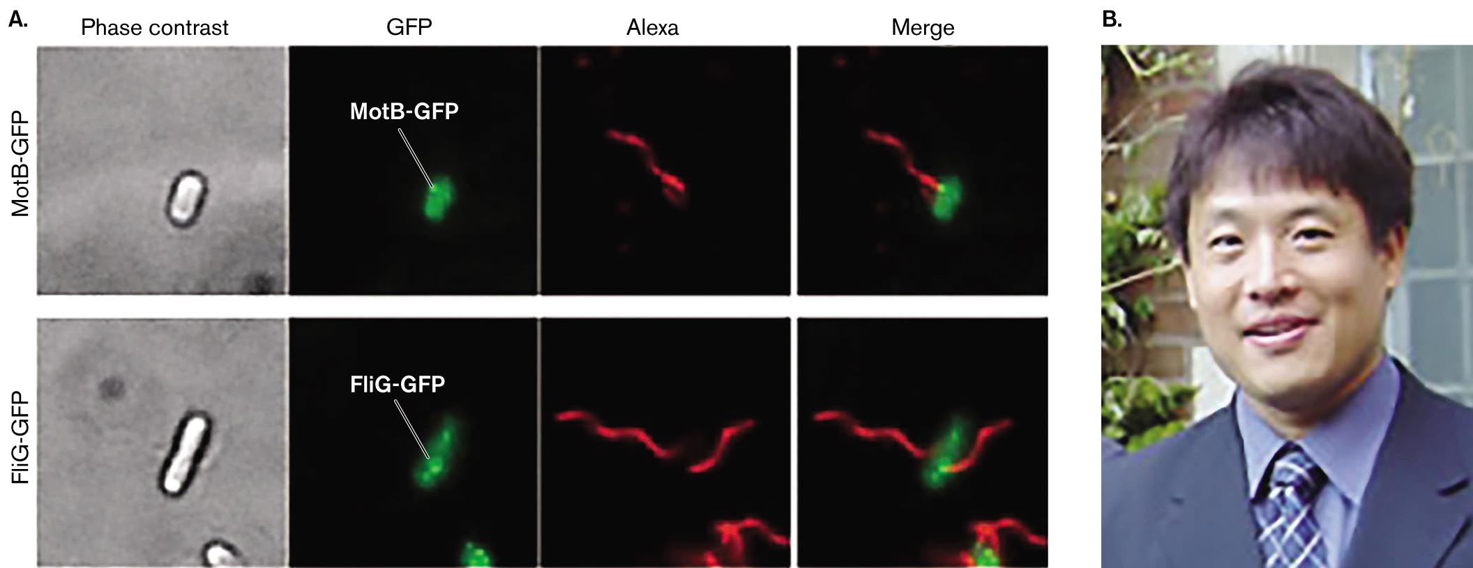
What kinds of experiments reveal the motor components? Results from an experiment dissecting the flagellar motor are shown in Figure 3.41. Japanese microbiologist Tohru Minamino (Osaka University) and colleagues constructed strains of Salmonella enterica in which the gene that encodes fluorescent GFP is fused to a gene encoding a flagellar protein, MotB or FliG, each of which is proposed to be a part of the motor. (Gene fusion is explained in Figure 2.29.) For each flagellar construct strain, fluorescence microscopy reveals the GFP fluorescence at one or two positions within the cell (green dots). A second fluorophore, Alexa, is conjugated to an anti-flagellin antibody. The Alexa fluorescence (red) reveals the flagellar filament. When the green and red fluorescence images are merged, the red flagellar filaments appear to extend from the motor positions that contain either MotB or FliG. Further experiments dissect the roles of key amino acid residues in the function of these proteins.
More information
A fluorescence microscopy series depicting flagellar motor proteins and a photo of Tohru Minamino.
A series of fluorescence microscopy images depicting the flagellar motor locations of M o t B - G F P and F l i G - G F P. The first series depicts M o t B - G F P. The first image in the series shows the unit under phase contrast microscopy. A small oval shaped structure is visible, it has a brightly lit center and a thick, dark border. The second image in the series shows fluorescently labeled G F P alone. G F P fluoresces green and appears as a small oval shaped structure. A white dot at the upper edge of the oval is labeled M o t B - G F P. The third image in the series is labeled Alexa. It shows a thin, strand like flagellum fluorescing red. The fourth image in the series is labeled merge. It shows the flagellum connected to the G F P unit at the white dot labeled M o t B - G F P. The flagellum fluoresces red and the G F P unit fluoresces green. The second series depicts F l i G - G F P. The first image in the series shows the unit under phase contrast microscopy. A long, rod shaped structure is visible, it has a brightly lit center and a thick, dark border. The second image in the series shows fluorescently labeled G F P alone. G F P fluoresces green and appears as a thin rod like shape with a tapered end. A bright dot within the shape is labeled F l i G - G F P. The third image in the series is labeled Alexa. It shows a thin, strand like flagellum fluorescing red. The fourth image in the series is labeled merge. It shows flagellum connected to the G F P unit at the bright dot labeled F l i G - G F P. The flagellum fluoresces red and the G F P unit fluoresces green.
A photo of Tohru Minamino wearing a suit and tie. He has black hair and brown eyes. He is smiling at the camera.
FIGURE 3.41 ■Flagellar motor proteins localized by fluorescence microscopy.A. Cells of Salmonella enterica express a GFP fused to flagellar motor protein MotB or FliG. Bright green dots (noted by white leader lines) indicate MotB-GFP or FliG-GFP complexed with a flagellar motor. The flagellar filament is visualized via the red fluorophore Alexa, conjugated to an anti-flagellin antibody. The merged image shows how each flagellar filament (red) extends from a motor containing either MotB or FliG (green, protein fused to GFP). B. Tohru Minamino investigates the structure and function of the flagellar motor. YUSUKE MORIMOTO ET AL. 2010. MOL. MICROBIOL.78:1117COURTESY OF PROTONIC NANOMACHINE GROUP, OSAKA UNIVERSITY
Note: Bacterial flagella differ completely from the whiplike flagella and cilia of eukaryotes and evolved separately. Eukaryotic flagella are much larger structures containing multiple microtubules enclosed by a membrane (shown in Chapter 20). They move with a whiplike motion, powered by ATP hydrolysis all along the flagellum.
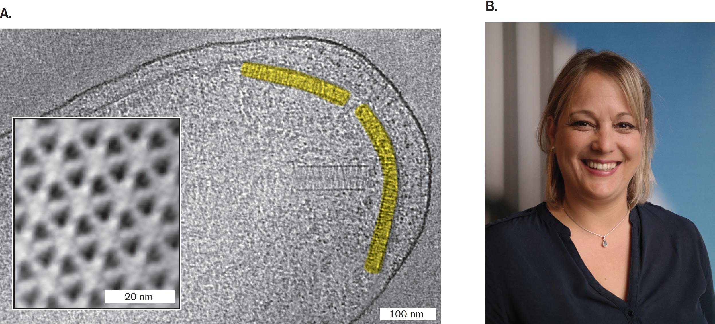
How do cells decide where to swim? Most flagellated cells have an elaborate sensory system for taxis, the ability to swim toward favorable environments (attractant signals, such as nutrients) and away from inferior environments (repellent signals, such as waste products). Taxis to specific chemicals is called chemotaxis. Chemotaxis requires receptors (chemoreceptors) that act like a “nose,” telling the bacterium when it is swimming toward a source of attractant such as a sugar or an amino acid. The attractant and repellent molecules are detected by arrays of chemoreceptors that are located near a cell pole (Fig. 3.42). This remarkably precise, ordered structure was first visualized in Gram-negative bacteria by Ariane Briegel and colleagues, at the California Institute of Technology and the University of Leiden. Figure 3.42 shows a TEM section of Vibrio cholerae, the cause of cholera. Briegel used cryo-electron tomography to identify the arrays at the cell pole, and she then used computation to define the repeated form of the array’s subunits.
More information
A cryo-electron tomograph of Vibrio cholerae and a photo of Ariane Briegel.
A cryo-electron tomograph of Vibrio cholerae. The cell is only partially visible and appears nearly transparent. The visible portion of the cell is about 500 nanometers wide and 800 nanometers long. Two curving bands are dyed yellow at one end of the cell. An inset image details the appearance of the receptor array.
An inset image detailing the cross section of a receptor array. The array appears as a pattern of uniform hexagons. Each hexagon is divided into 6 even triangles. One side of each hexagon is about 10 nanometers long.
A photo of Ariane Briegel smiling at the camera. She has blonde hair and brown eyes. She is wearing a blue blouse and a necklace.
FIGURE 3.42 ■Receptor array detects chemotactic signals for motility.A. Cryo-electron tomography section through Vibrio cholerae was used for digital reconstruction of chemotaxis receptor arrays. Inset: Cross section through an array. B. Ariane Briegel’s cryo-electron tomography team first imaged the Gram-negative receptor array.
Source: Ariane Briegel et al. 2016. PNAS113:10412.
A. BRIEGEL ET AL. 2016. PROC NATL ACAD SCI USA. 113:10412–7INSTITUTE OF BIOLOGY LEIDEN
Note: Chemotaxis control of motility, including the biased random walk, is covered in Section 12.1. Related topics of internalized flagella of spirochetes are shown in Section 18.5, and phototaxis (taxis toward light) for haloarchaea is presented in Section 19.5.
Besides motility and chemotaxis, surprisingly, flagella have also evolved an alternate function: adherence of cells to a substrate to begin forming a biofilm (discussed in Chapter 4). Thus, an organism can evolve a structure that serves one function but later evolves to serve another function.
In addition to flagellar rotation, other forms of bacterial motility are just beginning to be understood, such as pili-dependent twitching motility (discussed in Section 4.5). Another kind of motility, called “gliding,” is observed in cyanobacteria and in myxobacteria.
Thought Question
3.12 Most laboratory strains of E. coli and Salmonella commonly used for genetic research lack flagella. Why and how do bacterial strains evolve to lose flagella? How can a researcher maintain a motile strain?
ANSWER ANSWER
The motility apparatus requires 50 different genes generating different protein components. Cells that acquire mutations eliminating expression of the motility apparatus gain an energy advantage over cells that continue to invest energy in motors. In a natural environment, the nonmotile cells lose out in competition for nutrients, despite their energetic advantage; but in the laboratory, cells are cultured in isotropic environments such as a shaking test tube, where motility confers no advantage. These culture conditions lead to evolutionary degeneration of motility, as they do for the S-layer (see Thought Question 3.7). In order to maintain a motile strain, bacteria are cultured on a soft agar medium containing an attractant nutrient. As cells consume the attractant, they generate a gradient, and chemotaxis leads them to swim outward. By subculturing only bacteria from the leading edge of swimming cells, one can maintain a motile strain.
To Summarize
Cyanobacteria possess thylakoid membrane organelles packed with photosynthetic apparatus and carboxysomes for carbon dioxide fixation. Gas vesicles provide buoyancy in the water column.
Storage granules store elemental sulfur or organic carbon polymers for energy.
Adherence structures enable prokaryotes to remain in an environment with favorable environmental factors. Major adherence structures include pili or fimbriae (protein filaments) and the holdfast (a cell extension).
Flagellar motility involves rotary motion of helical flagella. Flagellar rotation is driven by the transmembrane proton motive force.
Chemoreceptors provide information that directs flagellar motility.
A filamentous structure for motility. In prokaryotes, a helical protein filament attached to a rotary motor; in eukaryotes, an undulating membrane-enclosed complex of microtubules and ATP-driven motor proteins.
A filamentous structure for motility. In prokaryotes, a helical protein filament attached to a rotary motor; in eukaryotes, an undulating membrane-enclosed complex of microtubules and ATP-driven motor proteins.
A micrograph of carboxysomes inside of a cell, and two detailed images of Rubisco complexes packed into a carboxysome. Part A is a transmission electron micrograph of a thin section of the lithoautotroph Halothiobacillus neapolitanus. Several carboxysomes can be seen inside each of the cells. The carboxysomes appear grainy and have circular shapes. Part B is a cryo electron tomograph of a carboxysome isolated from Synechoccus cyanobacterium. The carboxysome has a hexagonal shape. Many small circles are visible inside of the carboxysome. These circles are Rubisco complexes. Part C is a model of Rubisco complexes packed into a carboxysome. The Rubisco complexes are spherical and have bumpy surfaces.
A transmission electron micrograph of a thin section of the lithoautotroph Halothiobacillus neapolitanus. The micrograph is in greyscale. The H. neapolitanus cells have long, irregular shapes. Small grainy circles, identified as caboxysomes, can be seen inside of the cells. The carboxysomes have diameters of about 75 nanometers. The cells are each around 200 nanometers wide and 600 nanometers long.
A cryo electron tomograph of a carboxysome isolated from Synechoccus cyanobacterium. The tomograph is in greyscale. The carboxysome has a roughly hexagonal shape. Many tiny dark circles are visible inside of the carboxysome. These circles have been outlined in red and identified as Rubisco-complexes.
A model of Rubisco complexes inside of a carboxysome. The hexagonal shape of the carboxysome is outlined with a translucent grey. Rubisco complexes are packed inside of the carboxysome. The complexes are shown as spherical structures with bumpy surfaces.
FIGURE 15.7 ■Carboxysomes.A. Thin section of Halothiobacillus neapolitanus, a sulfur-oxidizing lithoautotroph (TEM), showing polyhedral carboxysomes (arrows). B. Carboxysome isolated from Synechococcus cyanobacterium is packed with Rubisco complexes (cryo-electron tomography). C. A 3D model of Rubisco complexes packed inside a carboxysome.
Source: Part A modified from Y. Tsai et al. 2007. PLoS Biol.5:E144.
COURTESY OF SABINE HEINHORST AND DR. GORDON C. CANNONC. V. IAN ET AL. 2007. J MOL BIOL. 372:764–773C. V. IAN ET AL. 2007. J MOL BIOL. 372:764–773
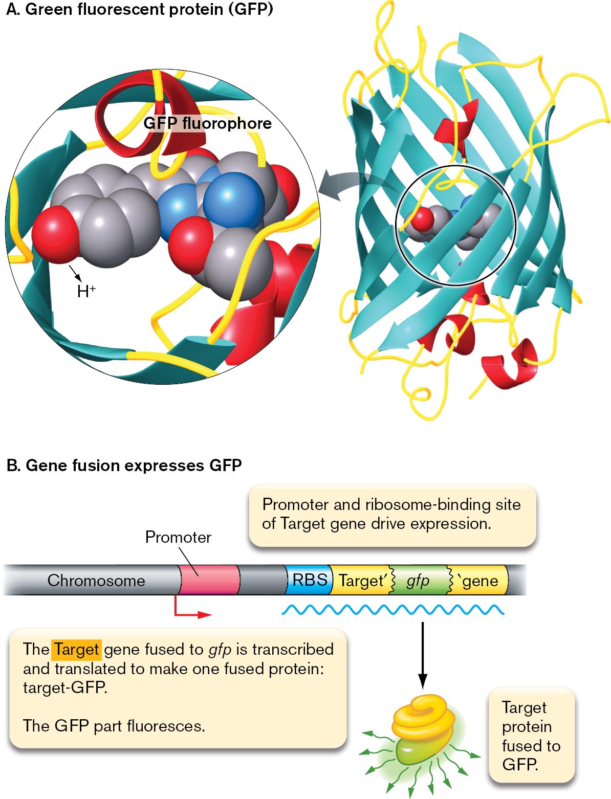
A model of G F P fluorophore and a model of G F P gene fusion.
A space filling model and the protein structure of G F P fluorophore are shown. The protein structure of G F P shows the fluorophore within barrel-shaped beta-sheets. A magnified view of the fluorophore shows a space-filling model of the three amino acids serine, tyrosine, and glycine, bonded.
A model of G F P gene fusion. A chromosome sequence has the promoter, R B S, target gene prime, g f p, and prime gene. An arrow points forward from the promoter, and an m R N A strand lies below the chromosome. From the m R N A strand, an arrow points down to show a truncated protein fused with another protein fluorescing. The fused protein is labeled, target protein fused to G F P. Accompanying text reads, The target gene fused to g f p is transcribed and translated to make one fused protein: target hyphen G F P. The G F P part fluoresces. Above the chromosome sequence, text reads, promoter and ribosome binding site of target gene drive expression.
FIGURE 2.29 ■The fluorophore green fluorescent protein (GFP).A. Green fluorescent protein (GFP) is expressed endogenously by the cell. Blowup: Three GFP amino acid residues (serine, tyrosine, and glycine) condense to form the fluorophore. B. The gene encoding GFP can be fused to a target gene (Target′-gfp). The fused gene then expresses a fused protein in which the GFP portion fluoresces. The fluorescent protein is expressed under control of the target gene promoter and ribosome-binding site (RBS).
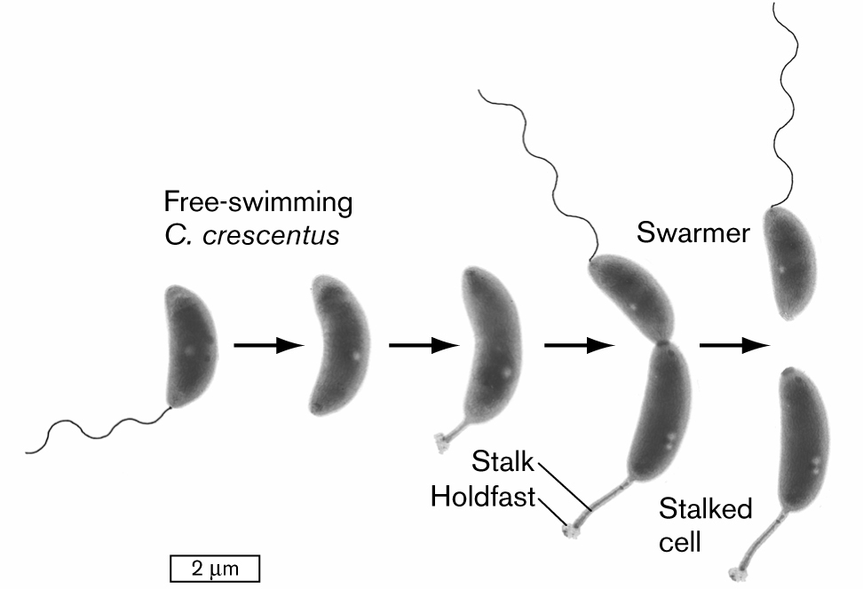
An illustration shows a developmental model for the division of an asymmetrical cell. It begins with a swarmer cell, which is a bean-shaped structure attached with a tail that is labeled as free-swimming C. crescentus. It leads to the next two images. The cell continues to elongate. There is a flagellum at one end of the cell and a stalk with a holdfast on the other end of the cell. The cell is pinched in the middle but still connected and leads to the division of two cells, in which one cell is attached with tail is labeled as a swarmer, and another cell is labeled as the stalked cell. The cell is about 2 micrometers long at the start and elongates to about 3 micrometers in length.
FIGURE 3.30 ■Asymmetrical cell division: a model for development. A swarmer cell of Caulobacter crescentus loses its flagellum and grows a stalk. The stalked cell divides to produce a swarmer cell (TEM). YVES BRUN
 ANSWER
 ANSWER