2.2 Hybrid Orbitals: Making a Model for Methane
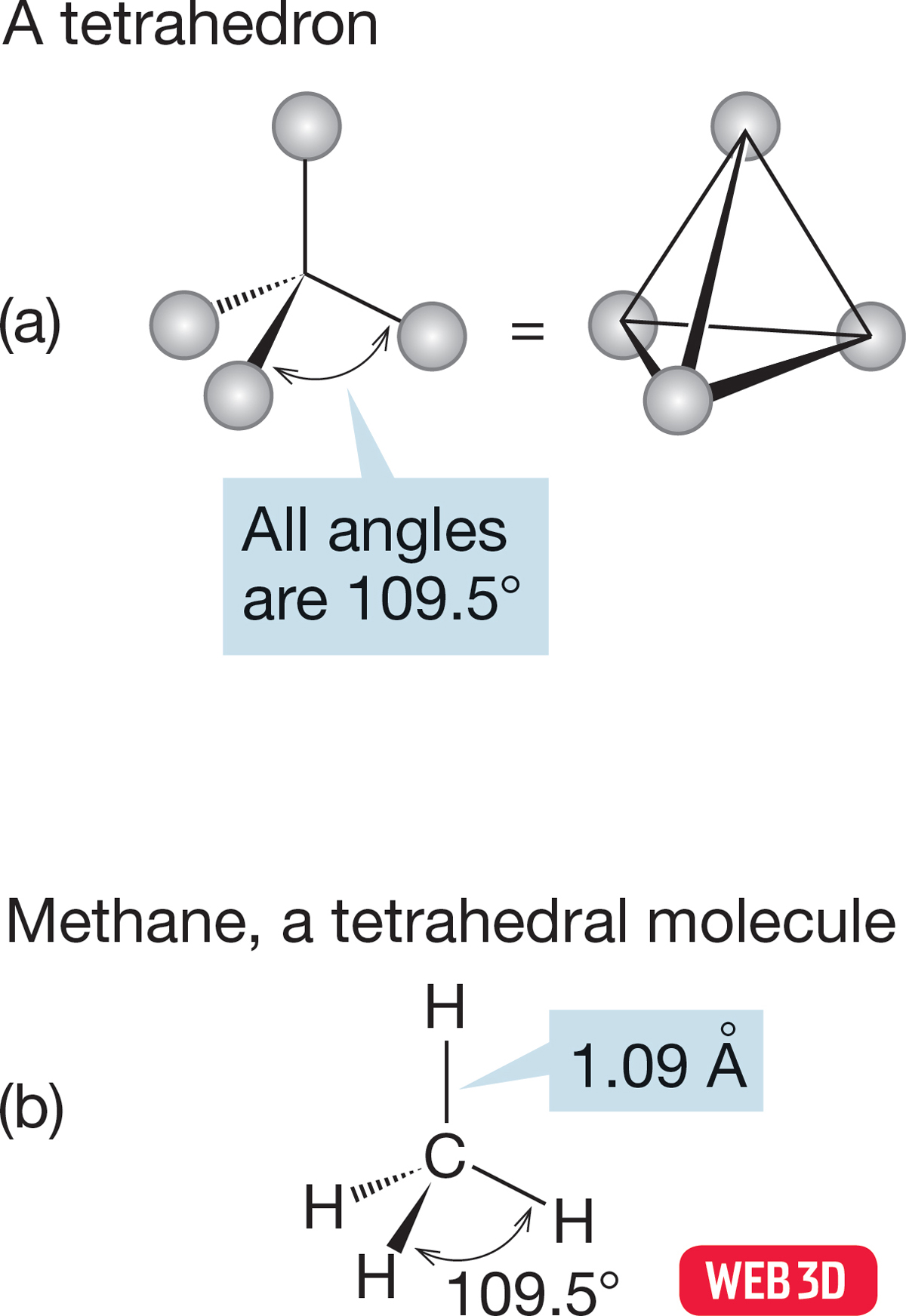
FIGURE 2.2 (a) A tetrahedron has four points symmetrically arranged and equidistant from the center. (b) A tetrahedral molecule, methane, showing the arrangement of the four hydrogens about the central carbon.
2.2a Hybridization Our task is to devise a bonding model for the structure of the simplest alkane, CH4, which is known as methane. Physical chemists tell us the structure: Methane is a tetrahedron, with all carbon–hydrogen bonds the same length (Fig. 2.2). We had an earlier look at a tetrahedron in Problem 1.5 (p. 16), in which the molecule carbon tetrachloride appeared. Our job now is to work out a bonding scheme that leads to the experimentally determined tetrahedral structure of methane.
The method we use to generate our model of methane goes by the name hybridization. Remember that we are working out a model, which means that no matter how useful it is, what we produce here is bound to be flawed in some respects. It is not the “ultimate truth” by any means! Our strategy is to combine the four atomic orbitals of a carbon atom (2s, 2px, 2py, 2pz) to produce four new orbitals—called hybrid orbitals—that can overlap with the 1s orbitals of four hydrogens to produce methane. Despite the fancy name hybridization, we are really doing something quite similar to the combining of atomic orbitals we saw often in Chapter 1, where we combined orbitals from different atoms to make molecular orbitals; here, we combine orbitals from the same atom to make hybrid atomic orbitals. Remember that we already know that a combination of four atomic orbitals must produce four new orbitals (p. 33).
It will greatly help our understanding of the hybridization process if we back up just a bit, examine the reasons for this model, and then look at two simpler hybridization models before we return to methane.
2.2b Why Hybridization? Why do we need to develop this new structural model called hybridization? If we want to form methane, why don’t we just overlap the 1s atomic orbitals of four hydrogens with the 2s and 2p atomic orbitals of carbon? Well, we certainly could have done just that, but the results are not very satisfying—this approach doesn’t give us a decent approximation of the structure of methane. However, let’s follow this simple procedure. We can learn a lot from examining what is wrong with models that are too simple. Also, what we do here approximates what really happens in science in that we make a series of successive structural approximations that come increasingly close to the real methane.
Figure 2.3 shows the overlap of the occupied carbon 2s, 2px, and 2py atomic orbitals with four hydrogen 1s orbitals. Two predictions are clear: First, we should form one C―H bond from the overlap of the carbon 2px orbital and one hydrogen 1s orbital and one C―H bond from the overlap of the carbon 2py orbital and another hydrogen 1s orbital; second, these bonds must be at 90° to each other because of the 90° angle between the carbon 2px and 2py orbitals. The third and fourth bonds are difficult to locate exactly, as they are formed from the overlap of a carbon 2s orbital with two hydrogen 1s orbitals. Both the 2s and 1s orbitals are spherically symmetric, and thus no directionality can be induced by the shape of the orbitals. We might guess that these two new carbon–hydrogen bonds would be oriented so as to keep the electrons in the bonds as far from each other as possible, thus minimizing repulsions.
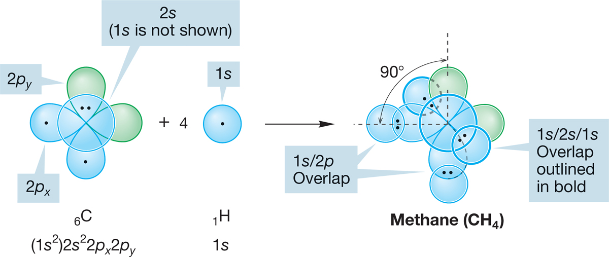
FIGURE 2.3 A possible structure for methane, CH4. Bonds are formed by the overlap of four hydrogen 1s orbitals with the 2p and 2s atomic orbitals of one carbon atom. This model requires some 90° bond angles and requires the bonds to be of different lengths. Carbon’s 1s electrons are shown in parentheses because they are not used in bonding.
PROBLEM 2.2 In a quick analysis, there appear to be too many electrons in the region of Figure 2.3 where the carbon 2s orbital and the two hydrogen 1s orbitals overlap. You might think that an atomic orbital with two electrons can’t make a bond with two other atoms, each bringing an electron. It is true that no orbital can have more than two electrons (the Pauli principle). You are used to thinking of two-electron bonds, and our new system is clearly more complicated than that. But there is no violation of the Pauli principle in the unhybridized model illustrated in Figure 2.3. Explain. Hint: Remember that overlap of n orbitals produces n new orbitals (p. 33).
The use of unhybridized carbon atomic orbitals to form methane—a model that yields the structure shown in Figure 2.3—has a fatal flaw. Modern spectroscopic methods show that there is no 90° H―C―H angle in methane and that all carbon–hydrogen bonds in the molecule are of equal length. Knowing that the structure shown in Figure 2.3 is wrong, we can begin to construct a model that does a better job of describing nature. Don’t be offended by this—science works this way all the time. The goal is to use what we learn from our wrong guesses to come closer next time. We can already anticipate one problem in this model: the electrons in some of the bonds are only 90° apart. They could be farther apart, and thus electron–electron repulsion could be reduced.
A second problem with the model used in Figure 2.3 might be labeled “inefficient overlap” or “wasted orbitals.” A 2p atomic orbital is poorly designed for efficient end-on overlap because overlap can take place only with one lobe. The back lobes of 2p orbitals are unused and thus wasted (Fig. 2.4). Our unhybridized model for methane has two such overlapping pairs of orbitals.
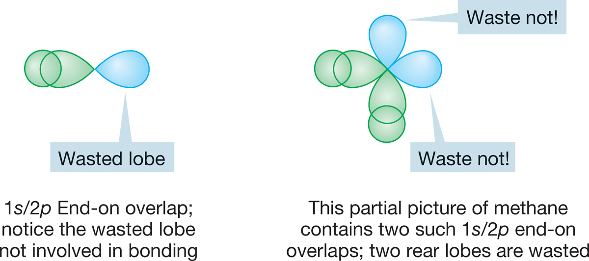
FIGURE 2.4 End-on overlap of a 2p atomic orbital with a 1s atomic orbital.
PROBLEM 2.3 Why not allow a 2p orbital to overlap sideways with an s orbital? Why would this not solve the problem of waste of the rear lobe (see Section 2.2c and Fig. 2.4)?
2.2c sp Hybridization Let’s first combine the 2s and 2px atomic orbitals from some arbitrary atom, as shown in Figure 2.5. The two can be combined in a constructive (2p + 2s) or a destructive (2p − 2s) way to create a pair of hybrid orbitals. These are atomic orbitals, so we can’t describe the hybrid orbitals as bonding or antibonding. Certainly, these hybrid orbitals will be involved in molecules, in which case we will see hybridized orbitals mixing to give bonding and antibonding molecular orbitals. Note in Figure 2.5 that the hybrid orbitals no longer have equal-sized lobes, as in a 2p orbital. In the 2p + 2s combination, we get an expansion of one of the original lobes (the one with the same sign as the 2s orbital) and a shrinking of the other (the one with the opposite sign). The second combination, 2p − 2s, is also lopsided, but in the opposite direction. These two new atomic orbitals are called sp hybrid orbitals. The designation sp means that the orbitals are composed of 50% s orbital (they have 50% s character) and 50% p orbital (they have 50% p character).
Figure 2.5 also shows the real shape of an sp hybrid orbital. It is traditional to use the schematic form in drawings, rather than attempt to reproduce the detailed structure of the orbital.
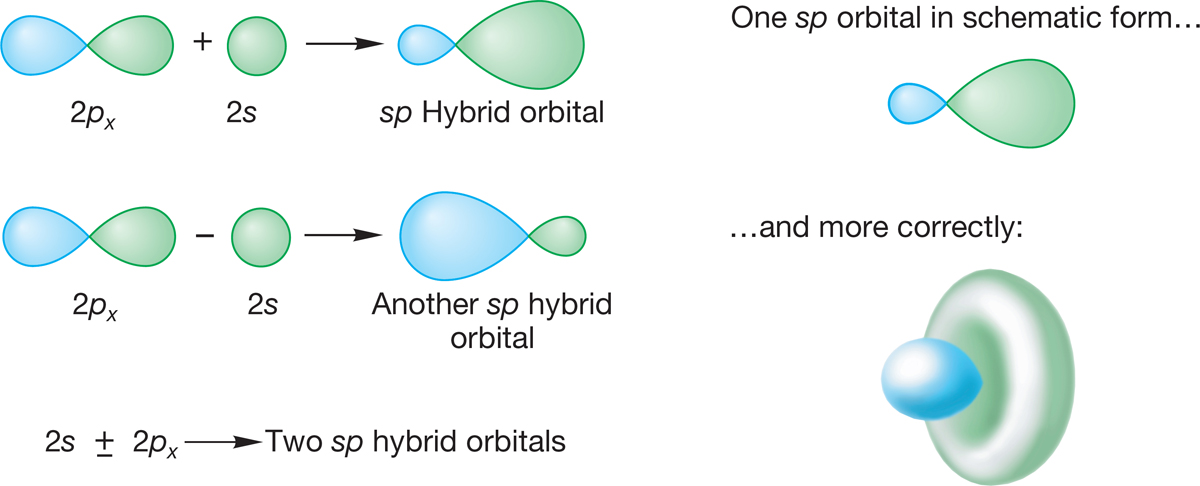
FIGURE 2.5 sp Hybridization.
Overlap between an sp orbital of one atom and an orbital of some other atom will be especially good if the fat lobe of the sp orbital is used (Fig. 2.6a). Contrast this overlap with the overlap when a 1s orbital overlaps with one lobe of a 2p orbital of another atom (Fig. 2.6b). The better the overlap, the greater the stabilization and the stronger the bond. In a sense, overlap of a 1s orbital with an unhybridized atomic 2p orbital “wastes” the back lobe of the 2p orbital. Hybridization improves overlap!
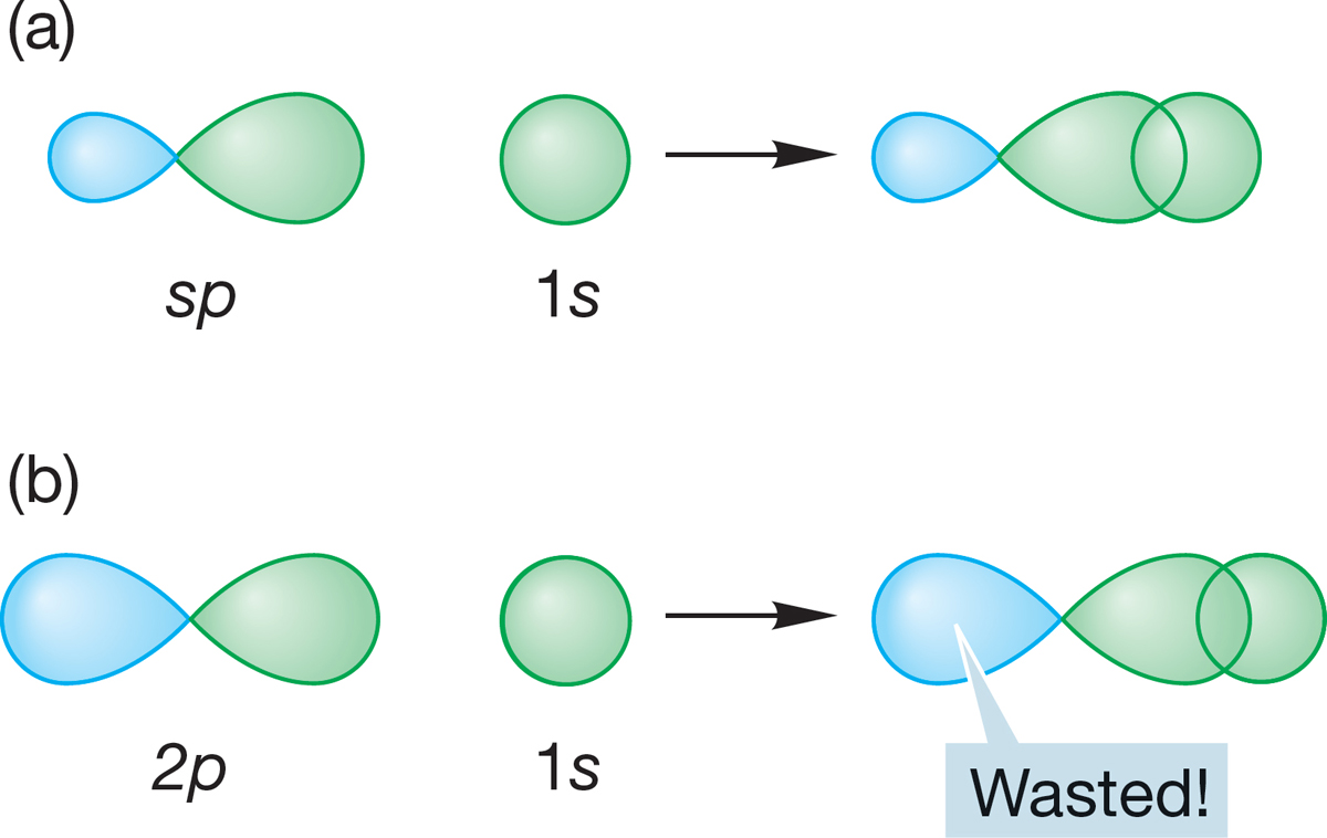
FIGURE 2.6 A comparison between overlap of a hydrogen 1s orbital with (a) an sp hybrid orbital and (b) an unhybridized 2p orbital. With the sp hybrid orbital, overlap is maximized because the non-overlapping back lobe is small. With the unhybridized 2p orbital, all of the non-overlapping back lobe is “wasted.”
Hybridization also minimizes electron–electron repulsion. The two new sp hybrid atomic orbitals formed from 2p + 2s and 2p − 2s (Fig. 2.5) are pointed 180° away from each other. The electrons in the bonds are as remote from each other as possible.
The sp hybrid can nicely describe the bonding in many compounds. The classic example is H―Be―H, a linear hydride of beryllium (Fig. 2.7). Beryllium (4Be) has the electronic configuration 1s22s2 and thus brings only two electrons to the bonding scheme (Remember: The filled-shell 1s electrons are not used for bonding.) We construct our picture of beryllium hydride (BeH2) by making two sp hybrid atomic orbitals from the Be 2s atomic orbital and one of the three equivalent Be 2p orbitals, arbitrarily taking the 2px orbital (which exists even though the configuration 1s22s2 tells us there are no electrons in this atomic orbital). The overlap of the 2px + 2s hybrid orbital with a singly occupied hydrogen 1s orbital and of the 2px − 2s hybrid orbital with a second hydrogen 1s orbital produces two Be―H bonds, directed at an angle of 180° with respect to each other. As a result of the linear shape of this compound, we say that the beryllium is sp hybridized.
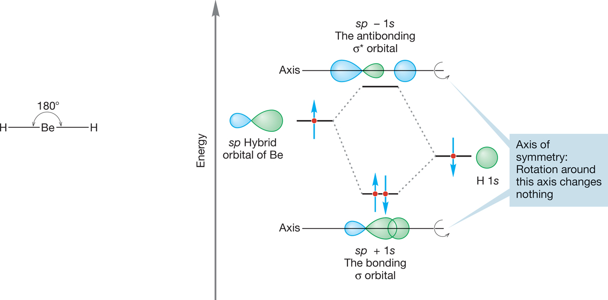
FIGURE 2.7 The formation of one bonding (σ) molecular orbital and one antibonding (σ*) molecular orbital from the overlap of a Be sp hybrid orbital with a hydrogen 1s atomic orbital. The interaction diagram shows that the 1s atomic orbital is at a lower energy than the sp hybrid orbital. The figure shows formation of only one of the two beryllium–hydrogen bonds in BeH2. The other Be—H bond is made in identical fashion through overlap of the second Be sp hybrid orbital with the 1s atomic orbital of a second H atom.
Bonds of this type, with cylindrical symmetry, are called sigma bonds (σ bonds). The orbital is unchanged through rotation around the axis between the Be and H. The combination of a Be sp orbital and an H 1s orbital produces the sigma bonding orbital (sp + 1s) and must also yield an antibonding orbital (sp − 1s), which in this case is empty, as shown in Figure 2.7. This antibonding orbital also has cylindrical symmetry and is therefore properly called a sigma antibonding orbital.
CONVENTION ALERT
Asterisk for Antibonding Orbitals
In Chapter 1, we used subscripts A and B to indicate antibonding and bonding orbitals (ФA, ФB), but from now on we can use the simpler notation of an asterisk (*) to indicate an antibonding orbital. Thus, in Figure 2.7, σ is the bonding molecular orbital sp + 1s and σ* is the antibonding molecular orbital sp − 1s.
It is no accident that we use two of beryllium’s atomic orbitals (2s and 2px) in our description of the bonding in BeH2. Two hybrid orbitals are needed for bonding to two hydrogens, which means we must combine two unhybridized atomic orbitals to get them.2
PROBLEM 2.4 What happens to the 2py and 2pz atomic orbitals of Be in BeH2? Elaborate the picture in Figure 2.7 to show your answer.
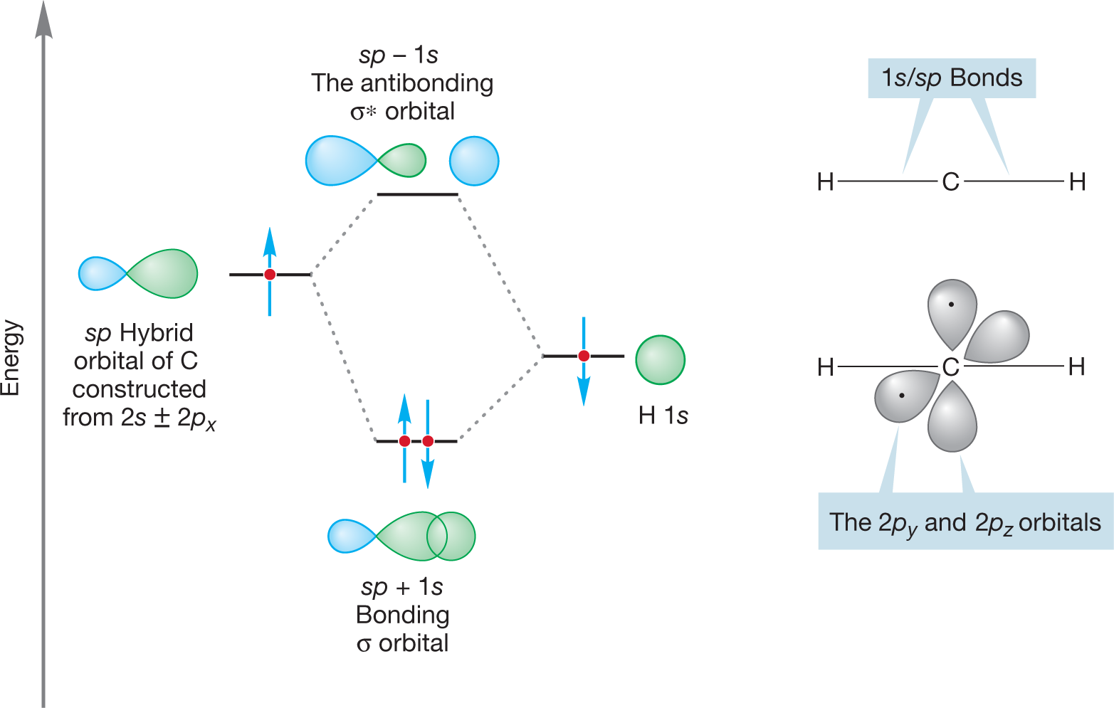
WORKED PROBLEM 2.5 Use the hybridization model to build a picture of the bonding in the linear molecule H―C―H.
ANSWER As with BeH2, the central atom, here carbon, is hybridized sp because the CH2 carbon only has two bonds. The 2s and 2px atomic orbitals of carbon are combined to form two sp hybrid orbitals (2s + 2px and 2s – 2px). One of the bonds in CH2 is made through overlap of the 2s + 2px sp hybrid orbital and the 1s atomic orbital of one hydrogen. The other bond is made through overlap of the 2s – 2px sp hybrid orbital and the 1s atomic orbital of the other hydrogen.
The 2py and 2pz atomic orbitals in the carbon remain unchanged. The atom uses two of its four bonding electrons in the carbon–hydrogen bonds, leaving two for the remaining 2p orbitals so that each p orbital contains a single electron.
2.2d sp2 Hybridization In BH3, we must make three boron–hydrogen bonds to form the molecule. The electronic configuration of boron (5B) is 1s22s22px, and thus there are three electrons available to form bonds with the three hydrogen 1s atomic orbitals. This time we combine the boron 2s, 2px, and 2py orbitals to produce the three orbitals we need in our model. These are called, naturally, sp2 hybrid orbitals (constructed from one s orbital and two p orbitals) and have 33% s character and 67% p character. They resemble the sp hybrid orbitals in appearance, shown in Figure 2.5. As with the sp orbital, the fat lobe of the sp2 orbital allows for efficient overlap with a hydrogen 1s or with any other orbital.
2s + 2px + 2py ➔ Three sp3 hybrid orbitals
PROBLEM 2.6 Consider the molecule trimethylaluminum. Draw a Lewis structure for this molecule, determine the formal charge, and predict the geometry around the aluminum and carbon atoms.
How are the three sp2 hybrid orbitals needed to form BH3 arranged in space? Your intuition may well give you the answer. They are directed so that electrons in them are as far as possible from one another. The angle between them is 120°, and they point toward the corners of a triangle (Fig. 2.8). An sp2 carbon and the three atoms surrounding it lie in the same plane. This shape is called trigonal planar.
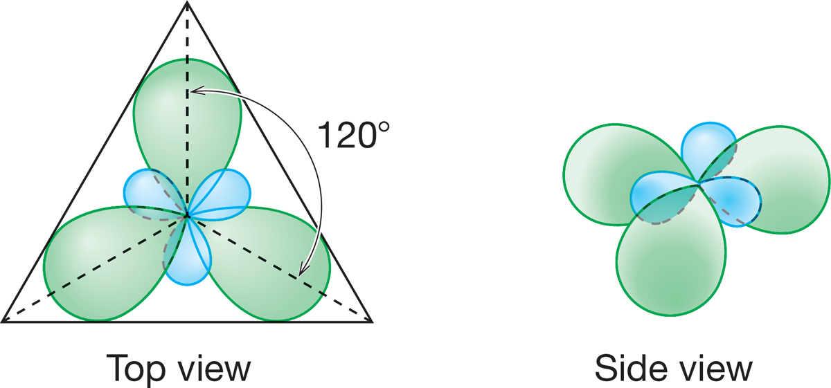
FIGURE 2.8 Top and side views of the arrangement in space of the three sp2 hybrid orbitals formed from the 2s, 2px, and 2py atomic orbitals of a boron atom.
PROBLEM 2.7 The 2pz orbital of boron was not used in our construction of the three sp2 hybrid atomic orbitals for the atom. Sketch it in, using the drawing of Figure 2.8.
2.2e sp3 Hybridization: Methane For CH4, we need four hybrid atomic orbitals because there are four hydrogens to be attached to carbon. Fortunately, we have just what we need in the 2s, 2px, 2py, and 2pz atomic orbitals of carbon. In our mathematical description, we combine these orbitals to produce four sp3 hybrid orbitals, which also look similar to sp hybrids (Fig. 2.5).
2s + 2px + 2py + 2pz ➔ Four sp3 hybrid orbitals
The familiar lopsided shape appears again, and thus we can expect strong bonding to the four hydrogen 1s atomic orbitals. By now, you will surely anticipate that these orbitals are directed in space so as to keep them, and any electrons in them, as far apart as possible. How are four objects arranged in space so as to maximize the distance between them? The answer is, at the corners of a tetrahedron (Fig. 2.2).
The carbon in methane is hybridized sp3 (25% s character; 75% p character), and the four hybrid atomic orbitals are directed toward the corners of a tetrahedron. The 1s atomic orbital in each of four hydrogen atoms overlaps with one of the four sp3 orbitals to form a bonding molecular orbital and an antibonding molecular orbital (Fig. 2.9). The resulting H―C―H angles are each 109.5°, and the length of a carbon–hydrogen bond in methane is 1.09 Å (Fig. 2.2).
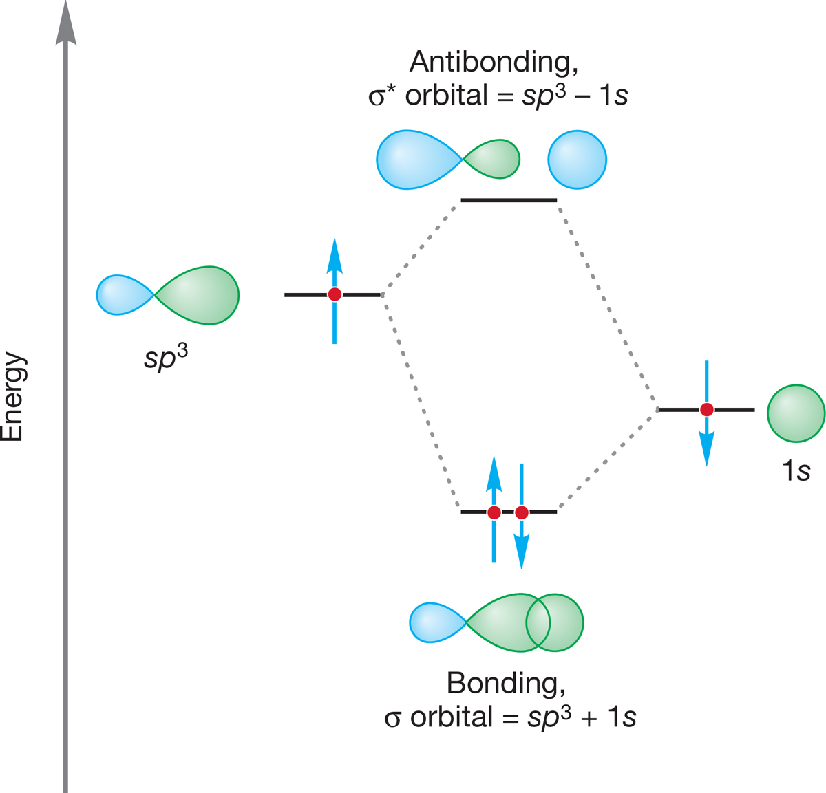
FIGURE 2.9 The formation of a carbon–hydrogen bond through the overlap of an sp3 hybrid orbital with a hydrogen 1s atomic orbital. Note the formation of both the bonding (σ) molecular orbital and the antibonding (σ*) molecular orbital.
The carbon–hydrogen bond in methane is very strong; its bond dissociation energy is 105 kcal/mol (440 kJ/mol). This means that 105 kcal/mol must be applied to break one of the carbon–hydrogen bonds in methane homolytically. This reaction is endothermic by 105 kcal/mol (Fig. 2.10). Compare this value to the bond strength of 104 kcal/mol for the very strong H―H bond in H2 (p. 37). The C―H bond in methane and the H―H bond in H2 have very similar strengths.
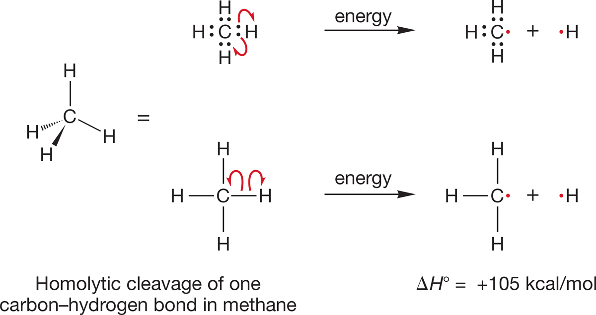
FIGURE 2.10 Two ways of showing homolytic cleavage of one carbon–hydrogen bond in methane. The top example shows the bonding electrons. The bottom example is the typical way to represent bonds. Each single-barbed arrow represents movement of one electron.
PROBLEM 2.8 Consider the ammonium ion (+NH4). Predict the hybridization of the nitrogen and the shape of the molecule.
Summary
There are three severe problems with the too-simple model for methane shown in Figure 2.3. The hybridization model solves each of them.
1. The electrons in the bonds are not as remote from each other as possible. The hybridization model yields four hybrid orbitals directed toward the corners of a tetrahedron, the best possible arrangement.
2. Bonds are formed through overlap between the carbon 2p atomic orbitals and hydrogen 1s orbitals in the simple model, thus wasting the back lobes of the 2p orbitals. In the hybridization model, overlap is much improved in the bonds formed using the fat lobes of sp3 orbitals and hydrogen 1s orbitals.
3. The four C―H bond lengths are not equivalent in the simple model. They are equivalent in the hybridized model.
Table 2.1 reviews the properties of sp, sp2, and sp3 hybrid orbitals.
TABLE 2.1 Properties of Hybrid Orbitals
Hybridization |
Constructed from |
Angle between Bonds (°) |
Examples |
|
sp |
50% s, 50% p |
180 |
BeH2, linear HCH |
|
sp2 |
33.3% s, 66.7% p |
120 |
BH3, BF3 |
|
sp3 |
25% s, 75% p |
109.5 |
CH4, +NH4 |
|
|
||||
Why didn’t we just tell you that methane is tetrahedral and be done with it rather than explore the unhybridized possibility? First of all, learning in science is not about gathering a collection of facts. Rather, it is about learning a way of thinking—a way of solving problems—to reach an approximate idea of how nature works. In science, we look at experimental data (methane has the formula CH4, for example) and then postulate a model to explain our observations. In the beginning, that model is almost certain to be either flawed or at the very least severely incomplete. So we test it against new data—against what can be learned from new experiments—and modify our hypothesis. In this case, that process looks like this: We find out that methane has no 90° angles. How can we change our model to get rid of those errors and come to a better model of nature? Ultimately, we come to the tetrahedral structure. We have learned much from looking at why our early, too-simple models were inadequate and from our process of investigation. You will forget most of the facts in this book, eventually. No matter: You can always look them up here or elsewhere. What we hope you will not forget is the investigative method used in organic chemistry and all other sciences—and many, many other disciplines as well.
We often hear students say, “Just tell us what will be on the exam.” But there is a purpose for giving you the comparison between an initial assumption of an unhybridized carbon and the more accurate model of the hybridized carbon. Being able to take data (i.e., the bond lengths and shape of methane) and apply it to a question (i.e., what orbitals are used in bonding in methane) is a skill called critical thinking. It is a skill you need to develop for this class. There is a fatal flaw in just giving the facts or just telling you what will be on the exam. Put simply, there is too much material in organic chemistry to memorize your way through it. You can survive at first, but somewhere about the middle of the first semester you will run out of memory, and there is no way (yet) to install any more. If you try to get through this year-long course by memorizing a set of facts, you will almost certainly not succeed. Success in organic chemistry—and in life really—depends on learning how to think critically; how to reason sensibly from new data. So that’s what we will try to do throughout this book, and we have begun right here.
METHANE
There is a lot of methane in very surprising places. Some anaerobic bacteria degrade organic matter to produce methane. When that process occurs deep in the ocean, water can crystallize in a cubic arrangement, encapsulating methane molecules to form hydrates called clathrates. And those clathrates can hold a lot of methane. One cubic meter of this hydrate could contain as much as 170 m3 of methane! Nor are those clathrates merely rare curiosities. Estimates vary, but the Arctic might hold as much as 400 gigatons, and worldwide estimates (guesses, really) run to as much as 10,000 gigatons. That’s a good news–bad news story. If we ever solve the daunting economic problems involved in finding these clathrates and getting the methane out, our hydrocarbon scarcity problems vanish for a long time. But, if that methane is ever released in an uncontrolled fashion (as it regularly is in science fiction disaster stories), watch out!
Lest you think that last scenario fanciful, as you read this, lakes in Siberia and Alaska, formed from melting permafrost, are bubbling with escaping methane. The University of Alaska’s Katey Walter Anthony, shown here setting one of those lakes afire, is investigating those burbling lakes. She and her associates suggest that earlier atmospheric methane spikes were at least partially the result of the escape of large amounts of this greenhouse gas.
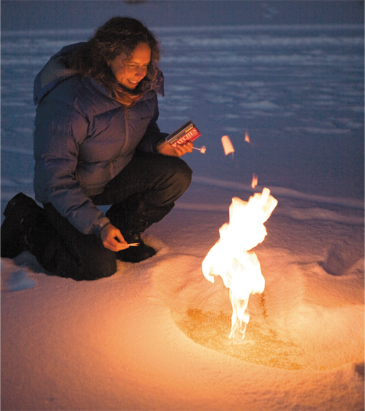
Dr. Katey Walter Anthony provides evidence of a flammable gas escaping from an Alaskan lake.
2Nothing in this discussion so far is specific to the element Be. Even though we are using this element as our example, we have been constructing hybrid orbitals for any second-row linear HXH molecule.